Transmission device of diaphragm jigger

The technology of a transmission device and a jig machine is applied in solid separation, chemical instruments and methods, wet separation, etc., and can solve the problems of unsatisfactory movement and separation of fine-grained stainless steel slag, low product quality, and poor sorting effect. Achieve the effect of wide range of use, high product quality and convenient adjustment

Pending Publication Date: 2020-05-19
CITIC HEAVY INDUSTRIES CO LTD
View PDF10 Cites 0 Cited by
  • Summary
  • Abstract
  • Description
  • Claims
  • Application Information

AI Technical Summary

Problems solved by technology

Therefore, due to the limitations of the structure of the transmission device, the traditional mining diaphragm jig machine is used for sorting stainless steel slag, the motion separation effect on fine-grained stainless steel slag is not ideal, the sorting effect is poor, the product grade is low, and the processing capacity Small

Method used


Image

  • Transmission device of diaphragm jigger
  • Transmission device of diaphragm jigger
  • Transmission device of diaphragm jigger

Examples


Embodiment Construction

[0033] The present invention can be explained in detail through the following examples, and the purpose of disclosing the present invention is to protect all technical improvements within the scope of the present invention.

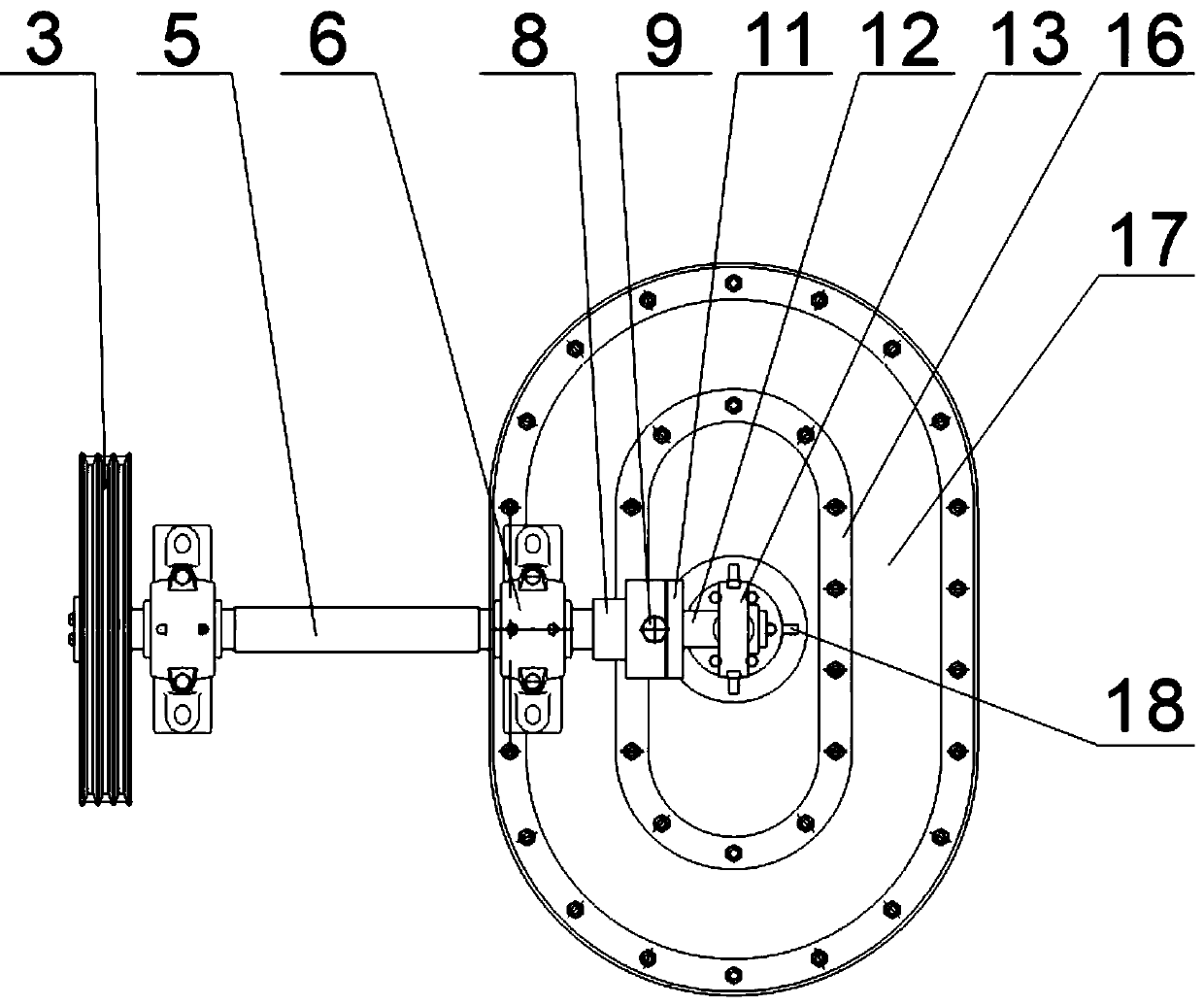
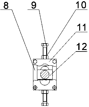
[0034] combined with Figure 1-8 As shown, a diaphragm jig transmission device of this patent includes a motor 1, a large pulley 3, a frame 4, two supporting bearing seats 6, a transmission shaft 5, a flat key 7, a coupling 8, and an eccentric shaft 12. Eccentric transmission mechanism 13, upper connecting rod 14, lower connecting rod 15 and pressure plate 16;

[0035] The output end of the motor 1 is connected with the large pulley 3 through the belt 2 to drive the large pulley 3 to rotate; two supporting bearing seats 6 are respectively arranged at the left and right ends of the frame 4; the transmission shaft 5 is arranged at the two supporting bearing seats 6 Inside, the left end of the transmission shaft 5 passes through the support bearing seat 6 o...


PUM


Abstract

The invention discloses a transmission device of a diaphragm jigger. The transmission device of the diaphragm jigger comprises a motor, a large pulley, a rack, two supporting bearing seats, a transmission shaft, a flat key, a coupler, an eccentric shaft, an eccentric transmission mechanism, an upper connecting rod, a lower connecting rod and a pressing plate; the output end of the motor is connected with the large pulley through a belt, and the two supporting bearing seats are respectively arranged at the left end and the right end of the rack; the transmission shaft is arranged in the two supporting bearing seats; a connecting block at the left end of the eccentric shaft is arranged in a rectangular groove on the right side of the coupler; the right end of the eccentric shaft penetrates through a strip-shaped hole of a cover plate and is connected with the eccentric transmission mechanism; the upper connecting rod is vertically arranged at the lower end of the eccentric transmission mechanism; the lower connecting rod is vertically arranged at the lower end of the upper connecting rod; and the pressing plate is horizontally arranged at the lower end of the lower connecting rod. Inthe working process of the jigger, the pressing-in of water has a remarkable movement separation effect on fine-grained stainless steel slag, the medium flow drives the movement state of materials tobe consistent, the fine-grained stainless steel slag can be well separated finally, the product grade is high, and the treatment capacity is large.

Description

technical field [0001] The invention belongs to the technical field of stainless steel slag sorting equipment, in particular to a mechanical diaphragm jig transmission device. Background technique [0002] Stainless steel slag is an important by-product produced in the stainless steel smelting process. Stainless steel slag contains stainless steel scrap composed of nickel, chromium and other precious metals. Recycling these precious resources can greatly reduce the cost of steelmaking. The problem of excessive discharge of metal ions in slag to pollute the environment. Considering economy and practicability, the separation of stainless steel slag can use diaphragm jig. [0003] Diaphragm jig is a gravity separation process that uses the vertical alternating medium flow caused by diaphragm vibration to loosen ore particles, thereby achieving stratification and separation according to density. Its characteristics are: strong water flow; loosening mainly depends on the pulsat...

Claims


Application Information

Patent Timeline
IPC IPC(8): B03B5/16B03B5/24
CPCB03B5/16B03B5/24
Inventor 姬国强屈冬婷张广伟高志明解华华
Owner CITIC HEAVY INDUSTRIES CO LTD
Why Eureka
Try Eureka