Motor rotor cleaning device

A technology for cleaning device and motor rotor, which is applied in the direction of dryer, drying gas arrangement, cleaning method and utensils, etc. It can solve the problems that the motor rotor cannot be cleaned, the difficulty of cleaning by cleaning personnel is high, and the normal operation of the motor is affected. Simple, manpower reduction, and convenient operation

Active Publication Date: 2020-05-19
CHANGZHOU FULING & CEIEC
View PDF5 Cites 3 Cited by
  • Summary
  • Abstract
  • Description
  • Claims
  • Application Information

AI Technical Summary

Problems solved by technology

[0002] The motor refers to an electromagnetic device that realizes the conversion or transmission of electric energy according to the law of electromagnetic induction. Its main function is to generate driving torque as a power source for electrical appliances or various machines. The motor rotor is also a rotating part in the motor. The motor rotor is divided into two types: the inner rotor rotation mode and the outer rotor rotation mode. The inner rotor rotation mode is the core body in the middle of the motor. body, output torque or energy input, the outer rotor rotates with the outer body of the motor as the rotating body, different methods facilitate the application in various occasions, the motor rotor needs to be cleaned after a long time of use, otherwise it will affect the normal operation of the motor At present, the commonly used cleaning methods include soaking method, spraying method, scrubbing method, etc., but these cleaning methods require manual cleaning, require a lot of manpower, and the cleaning personnel are difficult to clean, and the motor rotor cannot be completely cleaned.

Method used


Image

  • Motor rotor cleaning device
  • Motor rotor cleaning device
  • Motor rotor cleaning device

Examples


Embodiment Construction

[0017] All features disclosed in this specification, or steps in all methods or processes disclosed, may be combined in any manner, except for mutually exclusive features and / or steps.

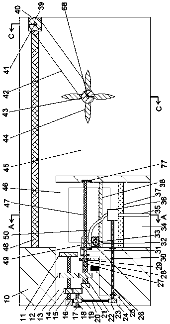
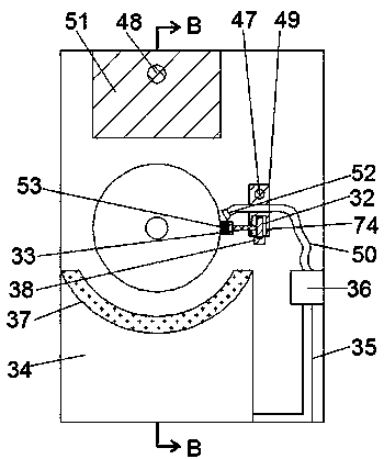
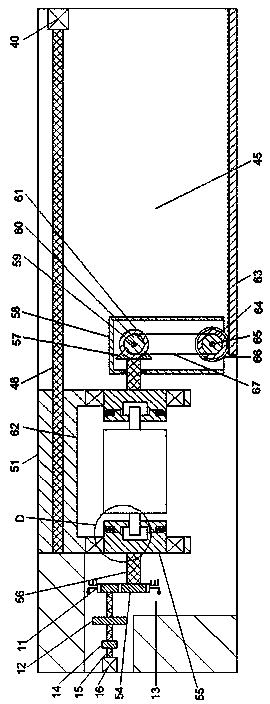
[0018] Combine below Figure 1-6 The present invention is described in detail, and for convenience of description, the orientations mentioned below are now stipulated as follows: figure 1 The up, down, left, right, front and back directions of the projection relationship itself are the same.

[0019] A motor rotor cleaning device of the device of the present invention includes a main body 10, a cleaning chamber 46 is provided in the main body 10, a cleaning assembly is provided in the cleaning chamber 46, and the cleaning assembly includes a cleaning assembly rotatably mounted on the cleaning chamber 46. The first screw rod 47 of the left and right end walls, the first screw rod 47 is provided with a first sliding block 49 through threaded cooperation, and the lower end wall of the first slid...


PUM


Abstract

The invention relates to the field of motors, in particular to a motor rotor cleaning device. The motor rotor cleaning device comprises a main body, wherein a cleaning cavity is formed in the main body, a cleaning assembly is arranged in the cleaning cavity and comprises first screws rotatably mounted on the left and right end walls of the cleaning cavity, a first slide block is arranged on each first screw in a screw fit manner, a transmission cavity communicating to the outer side is formed in the lower end wall of the first slide block, a first rotating shaft stretching backward to the outer side is rotatably mounted on the back end wall of the transmission cavity, a first gear fixedly connected to the first rotating shaft is arranged in the transmission cavity, and a cleaning brush isfixedly mounted at the back end of the first rotating shaft. After loading of the device, the motor controls a clamp to rotate to drive the motor rotor to rotate, and a hairbrush and a detergent slideleft and right and the hairbrush rotates. After cleaning, the clamp rotates while sliding rightward, the detergent left on the surface is thrown away by means of a centrifugal force, and meanwhile, afan rotates to accelerate surface drying of the motor rotor.

Description

technical field [0001] The invention relates to the technical field of motors, in particular to a cleaning device for motor rotors. Background technique [0002] The motor refers to an electromagnetic device that realizes the conversion or transmission of electric energy according to the law of electromagnetic induction. Its main function is to generate driving torque as a power source for electrical appliances or various machines. The motor rotor is also a rotating part in the motor. The motor rotor is divided into two types: the inner rotor rotation mode and the outer rotor rotation mode. The inner rotor rotation mode is the core body in the middle of the motor. body, output torque or energy input, the outer rotor rotates with the outer body of the motor as the rotating body, different methods facilitate the application in various occasions, the motor rotor needs to be cleaned after a long time of use, otherwise it will affect the normal operation of the motor At present,...

Claims


Application Information

Patent Timeline
Patent Type & Authority Applications(China)
IPC IPC(8): B08B3/02B08B3/08B08B3/14B08B1/04B08B13/00F26B5/08F26B21/00
CPCB08B1/002B08B1/008B08B1/04B08B3/02B08B3/08B08B3/14B08B13/00F26B5/08F26B21/001
Inventor 不公告发明人
Owner CHANGZHOU FULING & CEIEC
Why Eureka
Try Eureka