
Garbage recycling device and recycling method thereof

A technology for recycling and rubbish, applied in chemical instruments and methods, heating devices, cleaning methods and utensils, etc., can solve problems such as the inability to effectively collect and discharge liquid, the inability to discharge liquid accumulation, and the increase of structural complexity, etc. The effect of reducing damage, accelerating discharge, and reducing disposal costs

Pending Publication Date: 2020-05-19
深圳市君颂自动化科技有限公司
View PDF2 Cites 9 Cited by
  • Summary
  • Abstract
  • Description
  • Claims
  • Application Information

AI Technical Summary

Problems solved by technology

[0005] However, the overall structure of this device is complex, takes up a lot of space, and also has the following problems:
[0006] (1) The degreasing and desalting equipment 3 includes a drum 31, and the inner wall of the drum 31 is provided with a helical blade 311. Since the helical blade 311 is on the inner wall of the drum 31, to realize the rotation of the helical blade, it is necessary to rotate the drum as a whole to drive the helical blade. The leaves rotate, but the spray device 33 extends from the outside of the drum 31 to the inside of the drum 31, so obviously it needs to follow the rotation of the drum 31, and if the spray device 31 rotates, it will obviously increase the difficulty of supplying water to it, the design here is obvious unreasonable
[0007] (2) The cylinder wall of the drum 31 of the degreasing and desalting equipment is a screen structure, which can increase the drainage area in principle, but because there are many sticky substances in the wet garbage, such as dough, rice grains, etc., it is easy to block The mesh of the screen, so the large-area mesh further increases the problem of mesh blockage, which will inevitably affect the drainage efficiency; and because the cylinder wall is a screen structure, the discharged liquid needs to be collected through the liquid accumulation tank, and The size of the liquid accumulation tank needs to extend from one end of the drum 31 to the other end at least and cover the circumferential surface of the entire drum 31 as much as possible, which causes the size of the liquid accumulation tank to increase greatly
[0009] (4) The solid-liquid separation equipment is installed vertically, with the inlet facing downward and the outlet facing upward, and the screw propeller is used to transport the garbage upward. During the propulsion process, the garbage will fall under its own gravity, so it is bound to will reduce the efficiency of upward transport; in addition, in the process of transport, a large amount of liquid will inevitably accumulate at the inlet 511 under the action of gravity and cannot be discharged, and even if the liquid in the garbage is squeezed out, a large amount of water will not come out. The screen wall 512 is drained and accumulated, therefore, its liquid is often not collected and drained effectively
In addition, in this way, a screw conveyor needs to be set in the enclosure 54 to transport the material out, which obviously increases the complexity of the structure.

Method used


Image

  • Garbage recycling device and recycling method thereof
  • Garbage recycling device and recycling method thereof
  • Garbage recycling device and recycling method thereof

Examples


Embodiment Construction

[0052] Objects, advantages and features of the present invention will be illustrated and explained by the following non-limiting description of preferred embodiments. These embodiments are only typical examples of applying the technical solutions of the present invention, and all technical solutions formed by adopting equivalent replacements or equivalent transformations fall within the protection scope of the present invention.

[0053]In the description of the scheme, it should be noted that the terms "center", "upper", "lower", "left", "right", "front", "rear", "vertical", "horizontal", " The orientation or positional relationship indicated by "inner", "outer", etc. is based on the orientation or positional relationship shown in the drawings, and is only for the convenience of description and simplification of description, rather than indicating or implying that the device or element referred to must have a specific orientation , constructed and operated in a particular ori...


PUM


Abstract

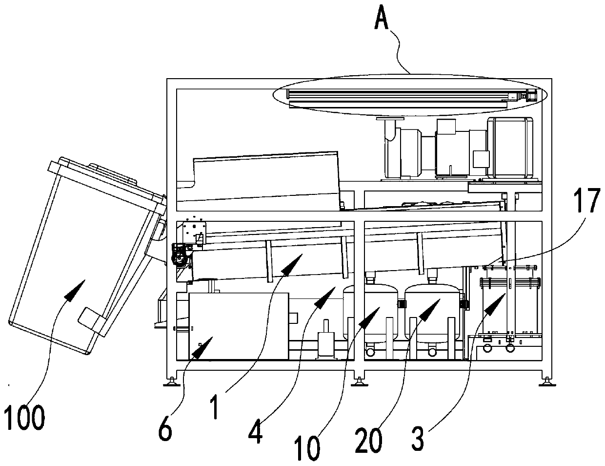
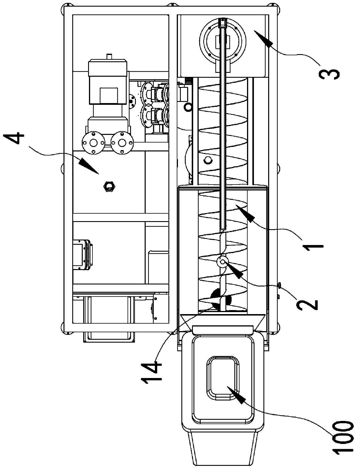
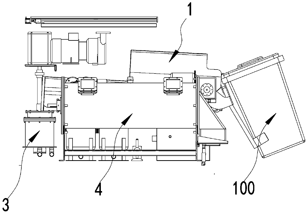
The invention discloses a garbage recycling device and a recycling method thereof. The garbage recycling device is used for processing kitchen waste and dry garbage, wherein the recycling device comprises a screw conveyor, a cleaning device, a crusher and a dryer; the screw conveyor comprises a material groove with high and low differences at two ends, the low end of the material groove is provided with a feed port, the bottom part of the barrel wall of the high end of the material groove is provided with a discharge port, and the bottom of the material groove is provided with a liquid discharge hole at the low end; the cleaning device is located above a screw conveying shaft in the material groove; the feed end of the crusher is hermetically connected to a discharge port of the screw conveyor, the dryer is connected with the discharging end of the crusher. According to the scheme, the garbage recycling device allows the liquid in the wet garbage to concentrate at a drainage hole underthe action of gravity to achieve emissions, so that the area of the drainage hole can be greatly reduced, in addition, a large size liquid collection groove is not required, and the difficulty of waste liquid collection is reduced; meanwhile, compared with existing oil and salt removing equipment, the design of the structure of the screw conveyor and the cleaning device is more reasonable, easier to realize, save a delivery crushing mechanism at the front end and more simple in structure.

Description

technical field [0001] The invention relates to the field of environmental protection equipment, in particular to a garbage recycling device and a recycling method thereof. Background technique [0002] Wet garbage refers to the garbage generated in the daily life of residents and food processing, catering services, unit meals and other activities, including discarded vegetable leaves, leftovers, leftovers, fruit peels, eggshells, tea residues, bones, animal viscera, fish scales , leaves, weeds, etc., the main sources of which are home kitchens, restaurants, restaurants, canteens, markets and other industries related to food processing. [0003] Wet garbage contains extremely high moisture and organic matter, which is easy to rot and produce bad smell. After proper treatment and processing, it can be transformed into new resources. The high organic matter content makes it possible to be used as fertilizer and feed after strict treatment, and can also produce biogas for fuel...

Claims


Application Information

Patent Timeline
IPC IPC(8): B09B3/00B08B9/093B08B3/02B02C21/00B02C18/10B02C18/22B30B9/14F26B23/04C05F9/02B65G65/23B01D17/02
CPCB09B3/00B08B9/093B08B3/022B02C21/00B02C18/10B02C18/2258B30B9/14F26B23/04C05F9/02B65G65/23B01D17/02Y02A40/20
Inventor 陈俊伟雷朝进
Owner 深圳市君颂自动化科技有限公司
Learn More