
Chained linear automatic brazing machine for air conditioner silencers

A technology of silencer and brazing machine, which is applied in welding equipment, auxiliary devices, applications, etc., can solve the problems of short welding time, poor solder penetration of welding joints, false welding temperature, etc., to achieve high welding efficiency and reduce production labor costs. , Consistent effect of welding quality standards

Pending Publication Date: 2020-05-19
佛山市高明德健五金有限公司
View PDF0 Cites 0 Cited by
  • Summary
  • Abstract
  • Description
  • Claims
  • Application Information

AI Technical Summary

Problems solved by technology

[0003] At present, the welding production of the above-mentioned air conditioner muffler is completed by 2-3 workers manually on a turntable equipped with tooling fixtures. One of the workers is responsible for loading and unloading, and the other workers are responsible for welding with welding torches. In the actual welding production During the process, the welding personnel work for a long time, and the personnel will be fatigued. The welding time may be too short, resulting in poor penetration of the solder inside the weld, too much or too little solder, false welding or uneven temperature, etc., and even Occurs that welders forget to fill nitrogen during welding operations
The welding production method of the existing air-conditioning muffler has high requirements on the skills of the operators, and welding defects are prone to occur, and each product needs to be cooled after welding, so the production efficiency is low

Method used


Image

  • Chained linear automatic brazing machine for air conditioner silencers
  • Chained linear automatic brazing machine for air conditioner silencers
  • Chained linear automatic brazing machine for air conditioner silencers

Examples


Embodiment Construction

[0025] Hereinafter, the present invention will be further described with reference to the accompanying drawings and specific embodiments to facilitate a clearer understanding of the technical ideas claimed by the present invention.

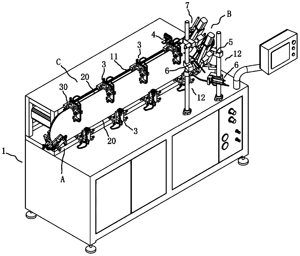
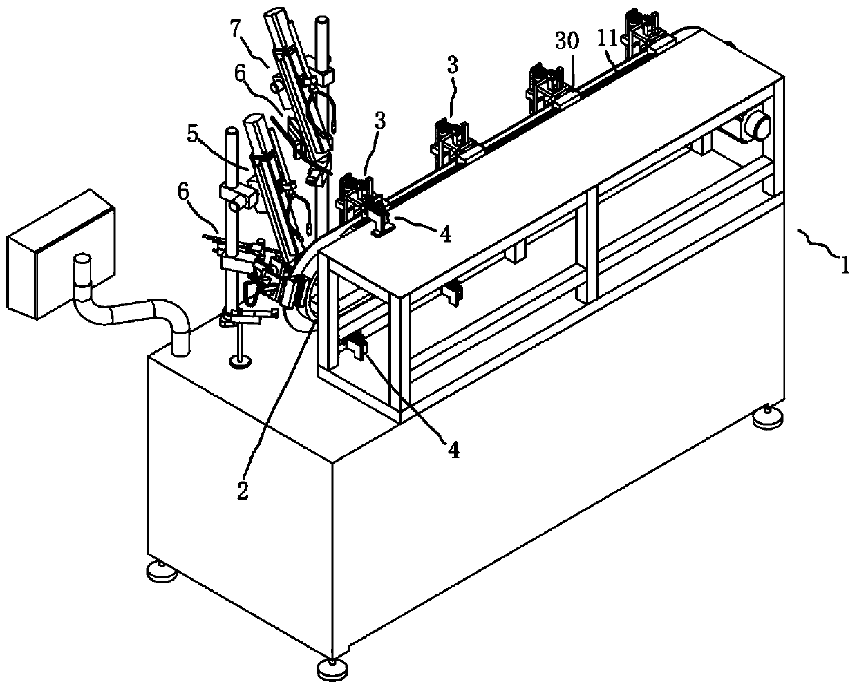
[0026] Such as Figure 2-10 A chain type linear automatic brazing machine for air conditioner silencer of the present invention is shown, comprising a frame 1, on which a circulating towline 2 is installed, and the circulating towline 2 has a pair of parallel linear conveying sections 20, on the frame 1 The linear guide rail 11 is installed corresponding to the linear conveying section 20, the fixture 3 is uniformly installed on the circulating drag chain 2, and the slide block 30 is installed on the fixture 3, and the fixture 3 on the linear conveying section 20 of the circulating drag chain 2 passes through the slide block 30 It is slidably connected with the linear guide rail 11 to realize the linear conveying movement. The structure of the slider...


PUM


Abstract

The invention discloses a chained linear automatic brazing machine for air conditioner silencers. The end, away from a first brazing device and a second brazing device, of a rack is a feeding and discharging area A, and the air conditioner silencers are positioned and fixed to tool clamps which are distributed and fixed to a circulating drag chain by a worker in the feeding and discharging area A;the air conditioner silencers are conveyed to the first brazing device and the second brazing device through the circulating drag chain, namely a welding area B is used for synchronously welding an expansion pipe, an air inlet pipe, an expansion pipe and an air outlet pipe of the air conditioner silencers on the tool clamps on the pair of parallel linear conveying sections of the circulating dragchain correspondingly; after the welded air conditioner silencers are linearly conveyed by the circulating drag chain to pass through a cooling area C, namely a linear guide rail area of the rack tobe cooled, a worker takes out the welded air conditioner silencers in the feeding and discharging area A and installs the new air conditioner silencer to be welded; and therefore air conditioner silencer welding machining is continuously and automatically completed, the welding efficiency is high, the welding quality standard is consistent, one-man operation is achieved, and the production labor cost is reduced.

Description

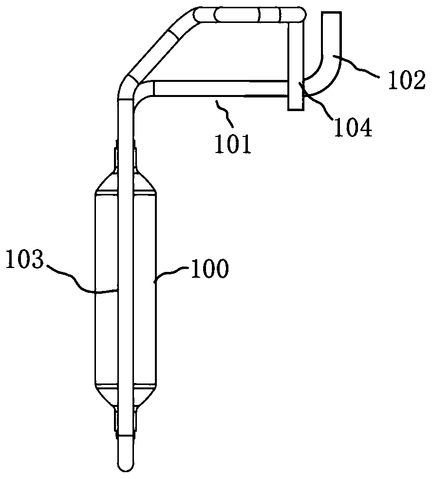
Technical field [0001] The invention belongs to the technical field of the production of air-conditioning silencers, and in particular relates to an air-conditioning silencer welding equipment. Background technique [0002] As attached figure 1 The air-conditioning muffler shown is composed of an expansion pipe 100, an air inlet pipe 101 and an air outlet pipe 103. The expansion pipe 100 is a stainless steel pipe. The upper and lower ends of the expansion pipe 100 shrink to form a necked end. The air inlet pipe 101 is a copper pipe and is welded to The upper end of the expansion pipe 100 is retracted, and the inlet pipe 101 is bent upward and forms an inlet pipe end 102 extending vertically upward by a circular arc transition at its end. The outlet pipe 103 is a copper pipe and is welded to the expansion pipe 100. The lower end shrinks the end, the outlet pipe 103 extends vertically downwards, then bends and extends upwards, and then bends and extends to form an outlet pipe end 1...

Claims


Application Information

Patent Timeline
Patent Type & Authority Applications(China)
IPC IPC(8): B23K3/08B23K101/06
CPCB23K3/08B23K3/087B23K2101/06
Inventor 张华石加华伦巨荣黄柄炎钟卫国
Owner 佛山市高明德健五金有限公司
Learn More