Automatic glazing device for ceramic spoon production

An automatic glazing device and ceramic technology, which is applied in the field of ceramic production, can solve problems such as troublesome operation, low work efficiency, and long installation and disassembly time, and achieve the effects of improving work efficiency, good thickness, and reducing worker workload

Active Publication Date: 2020-05-19
平邑仁安中医药产业发展有限公司
View PDF8 Cites 5 Cited by
  • Summary
  • Abstract
  • Description
  • Claims
  • Application Information

AI Technical Summary

Problems solved by technology

[0005] The object of the present invention is to provide an automatic glazing device for the production of ceramic spoons, in order to solve the existing process of glazing ceramic spoons proposed in the above background technology, it is necessary to manually hang the spoon on the tooling, and then The glazing is carried out by the glazing machine. After the glazing is completed, the spoon must be removed again. The operation is troublesome, the installation and disassembly time is long, and the work efficiency is low.

Method used


Image

  • Automatic glazing device for ceramic spoon production
  • Automatic glazing device for ceramic spoon production
  • Automatic glazing device for ceramic spoon production

Examples


Embodiment 1

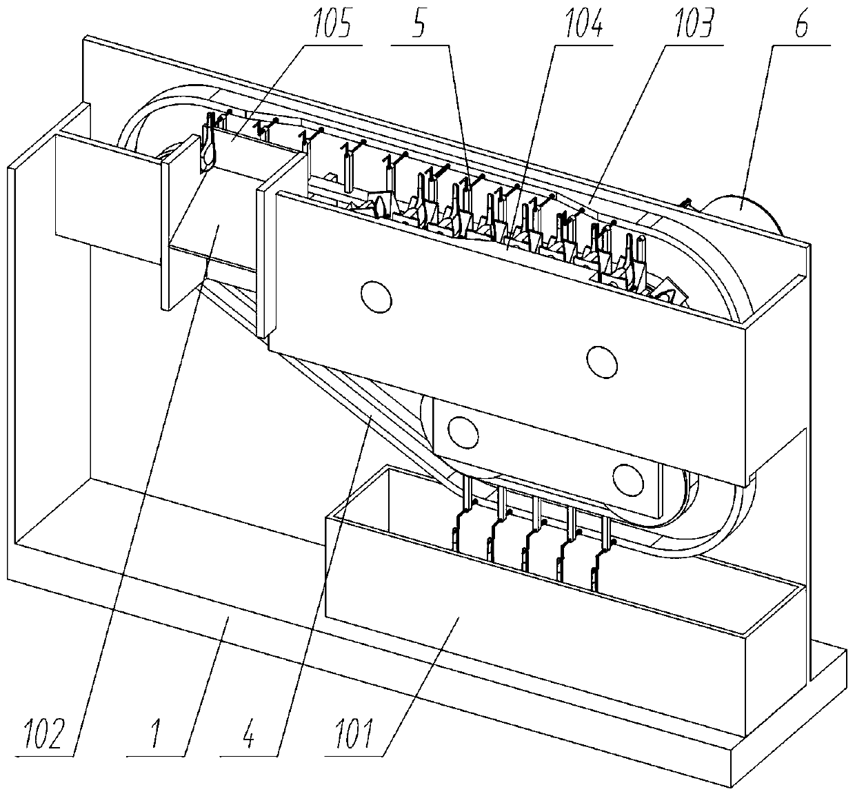
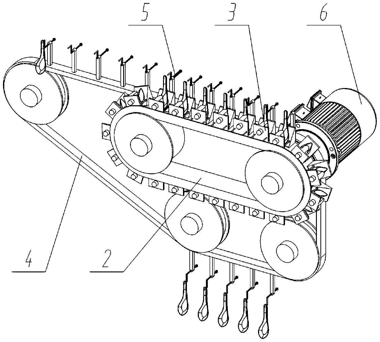
[0028] see Figure 1 to Figure 6 , an embodiment provided by the present invention: an automatic glazing device for the production of ceramic spoons, including a bracket main body 1; a group of glazing conveyor belts 4 and a group of positioning conveyor belts 2 are arranged on the upper inner rear side of the bracket body 1; A group of motors 6 are fixedly connected to the upper right side of the rear side of the bracket main body 1, and the motors 6 simultaneously drive the glazing conveyor belt 4 and the positioning conveyor belt 2 to rotate synchronously; the outside of the positioning conveyor belt 2 is evenly arranged with multiple sets of positioning devices 3; the positioning device 3 Also include fixed positioning block 301, sliding positioning block 302, fixed positioning block 301 is fixed on the bracket main body 1 of positioning device 3 rear side, the front end face of fixed positioning block 301 is slidably connected with a group of sliding positioning block 302,...

Embodiment 2

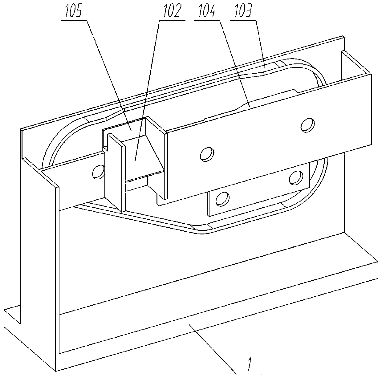
[0031] On the basis of Example 1, please refer to figure 1 , figure 2 with Figure 7 , an embodiment provided by the present invention: an automatic glazing device for ceramic spoon production, which also includes a hanging device 5, the hanging device 5 includes a hanging rod 501, a spline 502, and the hanging device The top of 5 is slidably connected with a group of hanging rods 501, the hanging rods 501 are Z-shaped structures, a group of splines 502 are arranged behind the hanging rods 501, and the hanging rods 501 are slidably connected with the hanging device 5 through the splines 502, And through the elastic connection of the spring, the hanging rod 501 is guided by the spline 502 in use; The bracket main body 1 also includes grabbing bosses 103, the rear portion of the bracket body 1 is provided with a group of ring-shaped grabbing bosses 103, the upper middle position of the grabbing bosses 103 is recessed toward the rear, and the ball head 503 is hung on the sprin...


PUM


Abstract

The invention discloses an automatic glazing device for ceramic spoon production, and relates to the technical field of ceramic production. The automatic glazing device for ceramic spoon production solves the problems that in the prior glazing process of a ceramic spoon, a spoon needs to be manually hung on a workpiece, a glazing machine is used for glazing, and after the glazing is completed, thespoon is removed again, the operation is troublesome, the mounting and dismounting time is long, and the working efficiency is low. The automatic glazing device comprises a bracket body, wherein a group of glazing conveying belts and a group of positioning conveying belts are arranged on the inner side of the bracket body, and a plurality of groups of hanging devices are uniformly arranged on theouter side of the glazing conveying belt. According to the device, the actions such as automatic hanging of the spoon, glazing of the spoon and automatic separation of the spoon can be realized, manual operation is greatly simplified, the workload of workers is reduced, and the working efficiency is improved; and meanwhile, the soaking time of the spoon in glaze can be better controlled, the thickness of the glaze can be better guaranteed, and the product quality is guaranteed.

Description

technical field [0001] The invention relates to the technical field of ceramic production, in particular to an automatic glazing device for the production of ceramic spoons. Background technique [0002] In ceramic production, it is often necessary to glaze ceramics to increase the mechanical strength and thermal stability of the product and to beautify the utensils. In the glazing of ceramic spoons, it is generally glazed by a glazing machine. [0003] For example, application number: CN201510002317.3 The present invention discloses a new type of automatic glaze dipping machine, which includes a base, a container is installed on the upper part of the base, a bracket is installed on one side of the upper part of the base, a motor frame is installed on one side of the bracket, and a swing motor is installed on the motor frame , a through hole is horizontally opened on the bracket, the output shaft of the swing motor passes through the through hole, one end of the output shaft...

Claims


Application Information

Patent Timeline
Patent Type & Authority Applications(China)
IPC IPC(8): B28B11/04
CPCB28B11/044
Inventor 李春杰
Owner 平邑仁安中医药产业发展有限公司
Why Eureka
Try Eureka