
Eureka
For R&D, Eureka makes reading and utilizing patents & technical documents easy.
Eureka AIR
Designed for self-driven R&D workflows. Generate viable solutions, solve complex R&D challenges, empower your innovation with AI.

Eureka Materials
Designed for material experts only. Revolutionize your material R&D, from search, analyze, to developing new materials.

TechResearch
Generate reliable direction feasibility study reports for your R&D in just a few steps.

TechSeek
Discover and master advanced knowledge NOW. Basics, ideas, possibilities, all at once.

TechMind
As an expert in R&D Theories, TechMind can generates customized viable solutions instantly.

TechRisk
Analyze your overall solution with one click, know your potential R&D risks in advance.

TechMonitor
Get weekly tech updates, stay abreast of the latest tech innovations and key insights.
Vertical bar-embedded sleeve type prefabricated underground diaphragm wall for foundation trench
A technology for underground diaphragm walls and vertical steel bars, applied in sheet pile walls, foundation structure engineering, excavation, etc., can solve the problem that the insertion depth of a single wall cannot meet the design requirements, is limited, and generally does not exceed 13~18m, etc.
- Summary
- Abstract
- Description
- Claims
- Application Information
AI Technical Summary
Problems solved by technology
Method used
Image

Examples
specific Embodiment 1
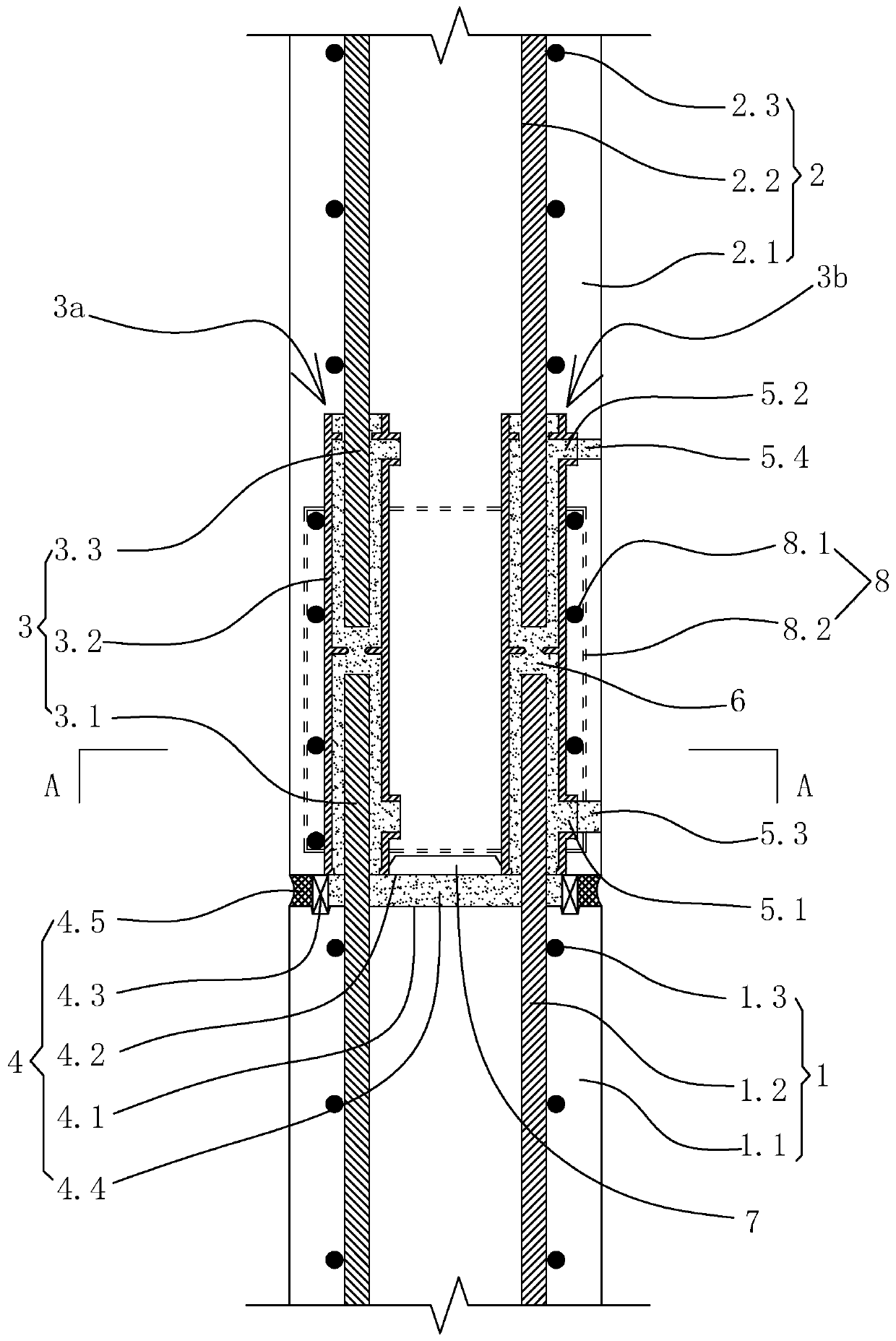
[0053] Specific embodiment one: as figure 1 , figure 2 , image 3 As shown, a kind of prefabricated underground diaphragm wall with vertical reinforcement pre-embedded sleeve type for foundation pit, including the lower prefabricated underground diaphragm wall 1, the upper prefabricated underground diaphragm wall 2, the front row of vertical connection components 3a, the rear row of vertical Connecting component 3b and horizontal seam sealing structure 4. The upper prefabricated underground diaphragm wall is supported on the top surface of the lower prefabricated underground diaphragm wall.
[0054] Such as figure 1 , figure 2 , image 3As shown, the lower prefabricated underground diaphragm wall 1 includes lower wall concrete 1.1, several lower wall vertical bars 1.2 pre-buried in the lower wall concrete and several lower wall horizontal distribution bars 1.3. The upper prefabricated underground diaphragm wall 2 includes the upper wall concrete 2.1, several upper wall...
specific Embodiment 2
[0072] Specific embodiment two, all the other structures of this embodiment refer to specific embodiment one, and its difference is:
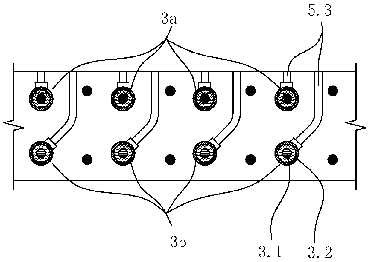
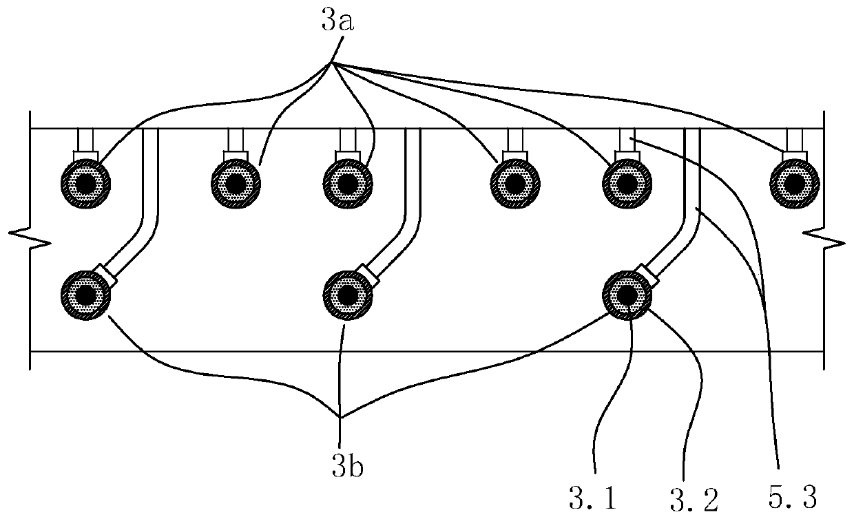
[0073] Such as Figure 7 As shown, the grouting hole 5.3 extends obliquely outwards and upwards from the grouting port 5.1. In this embodiment, the high-strength grouting material is injected through the grouting hole, and the specific construction steps of filling the high-strength grouting material in the gap between the positioning sleeve and the lower pre-embedded connecting column include: first, filling several steel balls in the grouting hole ; Second, pour high-strength grouting material into the grouting hole, so that the high-strength grouting material and the steel ball in the grouting hole are filled into the inner cavity of the positioning sleeve together; the steel ball is used to fill the inner surface and the lower surface of the positioning sleeve The gap between the pre-embedded connecting columns and the gap between the inne...
specific Embodiment 3
[0077] Specific embodiment three, all the other structures of this embodiment refer to specific embodiment one, and its difference is:
[0078] Such as Figure 8 , Figure 9 As shown, a sleeve-type prefabricated underground continuous wall with vertical reinforcement pre-embedded for a foundation pit also includes a pre-installed grouting device 9 . The preset grouting device includes a vertical grout storage tank 9.1 preset on the top surface of the lower prefabricated underground diaphragm wall 1, a grouting block 9.2 matched with the vertical grouting tank, and a support set on the side of the grouting block 9.3. The vertical grout storage tank is filled with high-strength grouting material, the grout block is supported on the top surface of the lower prefabricated underground diaphragm wall through the support, and the lower end of the grout block extends into the vertical grout storage tank, the side of the grout block There is a gap between it and the side wall of the...
PUM
 Abstract
Description
Claims
Application Information
 - R&D Engineer
- R&D Manager
- IP Professional
- Industry Leading Data Capabilities
- Powerful AI technology
- Patent DNA Extraction
Browse by: Latest US Patents, China's latest patents, Technical Efficacy Thesaurus, Application Domain, Technology Topic, Popular Technical Reports.
© 2024 PatSnap. All rights reserved.Legal|Privacy policy|Modern Slavery Act Transparency Statement|Sitemap|About US| Contact US: help@patsnap.com