
Hydraulic rotation control system of dynamic compaction machine

A technology of control system and dynamic compaction machine, applied in mechanical equipment, fluid pressure actuating device, servo motor, etc., can solve the damage to the pinion gear of the slewing device and the large ring gear of the slewing support, the high cost and overload of the closed slewing hydraulic system The valve effect is not obvious and other problems, to achieve the effect of safety assurance, reduction of maintenance costs, and smooth braking

Pending Publication Date: 2020-05-19
HANGCHA GRP +1
View PDF0 Cites 1 Cited by
  • Summary
  • Abstract
  • Description
  • Claims
  • Application Information

AI Technical Summary

Problems solved by technology

[0003] The existing hydraulic slewing control system of dynamic compaction machine mainly adopts overload valve or overload valve with delay boost, and external control controller; or adopts closed hydraulic control system to ensure the stability and safety of the system, but it is difficult to Absorb the impact of the system. If the impact is large, it is easy to cause damage to the small gear of the slewing device and the large ring gear of the slewing support, thereby increasing the maintenance cost; the effect of using the overload valve with delay boost is not obvious; the cost of the closed slewing hydraulic system is relatively high

Method used


Image

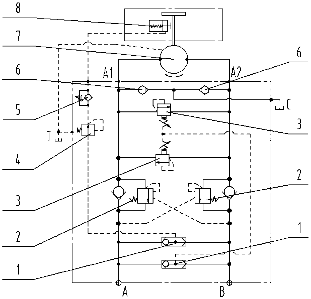
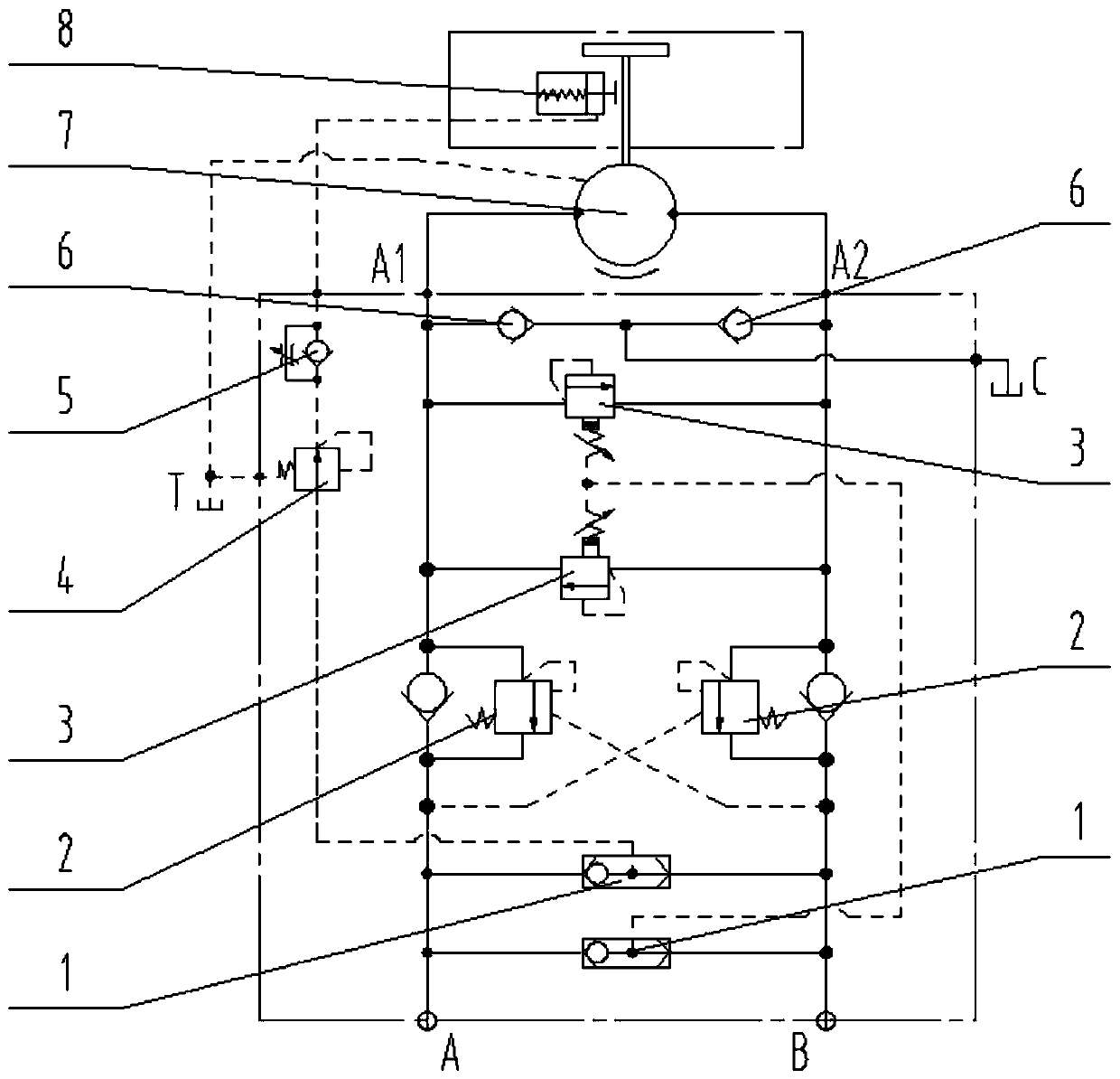
  • Hydraulic rotation control system of dynamic compaction machine
  • Hydraulic rotation control system of dynamic compaction machine

Examples


Embodiment Construction

[0020] The following will clearly and completely describe the technical solutions in the embodiments of the present invention with reference to the accompanying drawings in the embodiments of the present invention. Obviously, the described embodiments are only some, not all, embodiments of the present invention. Based on the embodiments of the present invention, all other embodiments obtained by persons of ordinary skill in the art without making creative efforts belong to the protection scope of the present invention.

[0021] Please refer to figure 1 , figure 1 It is a schematic diagram of the control principle of a hydraulic rotary control system of a dynamic compaction machine provided by a specific embodiment of the present invention.

[0022] A hydraulic rotary control system for a dynamic tamping machine provided in an embodiment of the present invention includes: a two-way quantitative hydraulic motor 7, a shuttle valve 1, a balance valve 2, and a buffer valve 3. The ...


PUM


Abstract

The invention discloses a hydraulic rotation control system of a dynamic compaction machine. The system comprises a two-way quantitative hydraulic motor, a shuttle valve, a balance valve and a cushionvalve. Two oil inlets of the two-way quantitative hydraulic motor are each connected with one oil supply line. The shuttle valve, the balance valve and the cushion valve are arranged between the twooil supply lines in a connected manner. The shuttle valve is used to supply oil to the cushion valve. An oil inlet and an oil outlet of the cushion valve are located on the two oil supply lines respectively, and are located between the balance valve and the two-way quantitative hydraulic motor. After rotation operation stops, the balance valve plays a role in hydraulic braking; after rotation stops suddenly, because of the inertia of the motor, the pressure of an oil return chamber rises, and when the pressure rises to a set pressure, because the cushion valve loses balance at the moment, a higher chamber and a lower chamber communicate with each other, a peak pressure will disappear, and shaking impact of a complete machine will not happen; and additionally, compared with a traditional overload valve or an overload time delay valve system, the cushion valve directly adopts rotation pressure control, and thereby being capable of meeting the requirement for control in time, and then theresponse speed is high.

Description

technical field [0001] The invention relates to the technical field of dynamic ramming machines, in particular to a hydraulic rotary control system of a dynamic ramming machine. Background technique [0002] As the dynamic compaction machine develops towards a higher energy level, the weight of the whole machine is getting heavier and heavier. Therefore, higher requirements are put forward for the safety and comfort of the hydraulic system, especially for driving the mast or the tamper to rotate. Smooth and safe. [0003] The existing hydraulic slewing control system of dynamic compaction machine mainly adopts overload valve or overload valve with delay boost, and external control controller; or adopts closed hydraulic control system to ensure the stability and safety of the system, but it is difficult to Absorb the impact of the system. If the impact is large, it is easy to cause damage to the small gear of the slewing device and the large ring gear of the slewing support,...

Claims


Application Information

Patent Timeline
IPC IPC(8): F15B11/08F15B13/042
CPCF15B11/08F15B13/042F15B2211/505F15B2211/7058
Inventor 胡艳华高敏包奇李宗杰
Owner HANGCHA GRP
Learn More