Medical waste pollution-free combustion treatment device
A technology for medical waste and treatment devices, which is applied in combustion types, grain treatment, gas treatment, etc., can solve problems such as insufficient crushing, drying and incineration, and achieve the effect of easy discharge and separation
- Summary
- Abstract
- Description
- Claims
- Application Information
AI Technical Summary
Problems solved by technology
Method used
Image

Examples
specific Embodiment approach 1
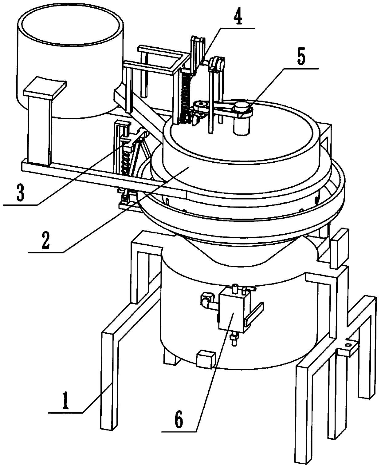
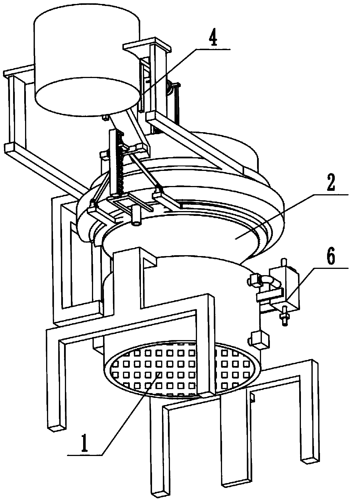
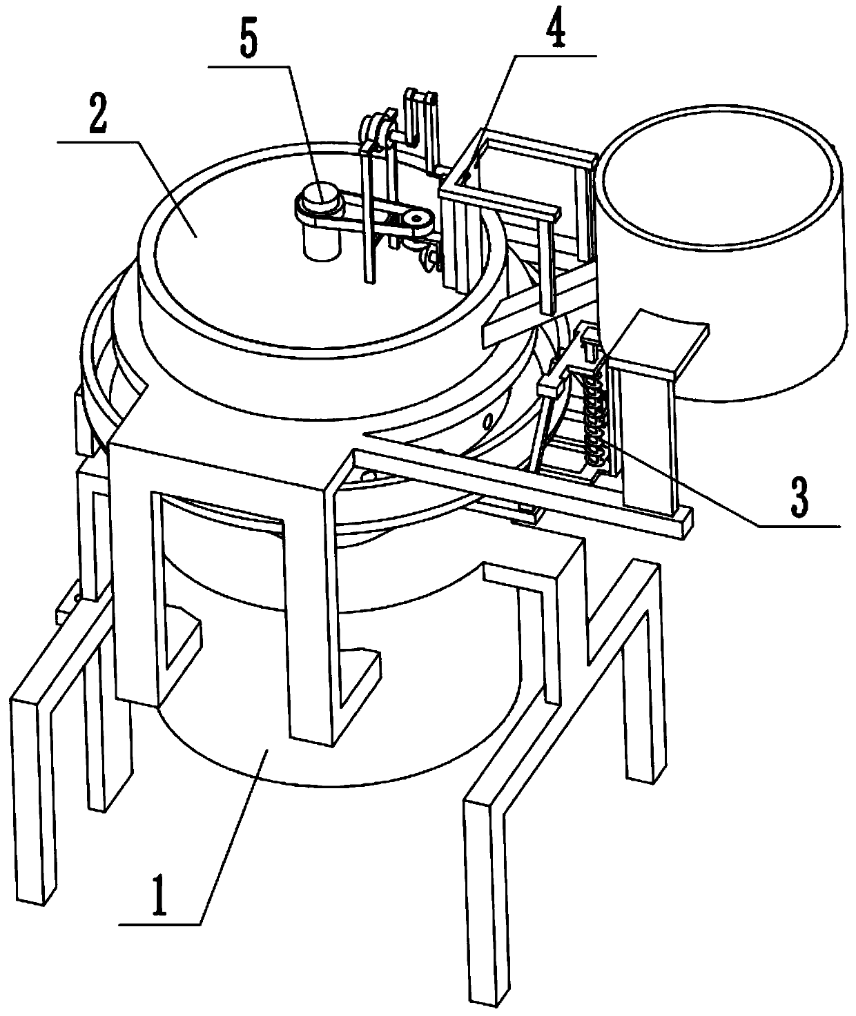
[0032] Combine below Figure 1-13 Describe this embodiment, a pollution-free combustion treatment device for medical waste, including a feeding and combustion device 1, a liquid medicine separation component 2, an automatic discharge mechanism 3, a compression crushing mechanism 4, a stirring mechanism 5, and an exhaust gas treatment mechanism 6. The waste gas treatment mechanism 6 described above is arranged at the lower end of the feeding and burning device 1, the chemical liquid separation assembly 2 is arranged at the middle of the feeding and burning device 1, and the chemical liquid separating assembly 2 communicates with the upper end of the feeding and burning device 1, automatically The discharge mechanism 3 is set on the liquid medicine separation assembly 2, the compression crushing mechanism 4 is set on the liquid medicine separation assembly 2, the left end of the compression crushing mechanism 4 corresponds to the left end of the automatic discharge mechanism 3, a...
specific Embodiment approach 2
[0034] Combine below Figure 1-13 To illustrate this embodiment, the described feeding and combustion device 1 includes a combustion chamber 1-1, an igniter 1-2, a fire grate 1-3, a side frame 1-4, a cylinder frame 1-5, and a fixed plate 1-6 , feeding cylinder 1-7 and material guide seat 1-8; combustion chamber 1-1 is fixedly connected between two side frames 1-4, and combustion chamber 1-1 is provided with igniter 1-2, combustion chamber 1- The lower end of 1 is provided with a fire grate 1-3, and the cylinder holder 1-5 is fixedly connected to the combustion chamber 1-1, and the feeding cylinder 1-7 is fixedly connected to the cylinder holder 1-5 through two fixing plates 1-6. The lower end of the feed cylinder 1-7 is fixedly connected and communicated with the material guide seat 1-8; the liquid medicine separation assembly 2 is arranged on the cylinder frame 1-5; the upper end of the combustion chamber 1-1 is provided with a movable door. The rubbish is put into the feedi...
specific Embodiment approach 3
[0036] Combine below Figure 1-13 To illustrate this embodiment, the liquid medicine separation assembly 2 includes a separation cylinder 2-1, a top cover 2-2, a liquid medicine discharge hole 2-3, an annular water receiving seat 2-4, and a drain pipe 2 with a control valve. -5 and bottom plate chute 2-6; the upper end of the separation cylinder 2-1 is fixedly connected to the top cover 2-2, and the lower end of the separation cylinder 2-1 is evenly surrounded by a plurality of liquid medicine discharge holes 2-3, and an annular water receiving seat 2-4 is fixedly connected to the separation cylinder 2-1, the lower end of the annular water receiving seat 2-4 is fixedly connected and communicated with two drain pipes 2-5, and the lower end of the separation cylinder 2-1 is provided with a floor chute 2-6; The annular water receiving seat 2-4 is located between the liquid medicine discharge hole 2-3 and the bottom plate chute 2-6; the separation cylinder 2-1 is fixedly connected...
PUM
 Abstract
Description
Claims
Application Information
 - R&D
- Intellectual Property
- Life Sciences
- Materials
- Tech Scout
- Unparalleled Data Quality
- Higher Quality Content
- 60% Fewer Hallucinations
Browse by: Latest US Patents, China's latest patents, Technical Efficacy Thesaurus, Application Domain, Technology Topic, Popular Technical Reports.
© 2025 PatSnap. All rights reserved.Legal|Privacy policy|Modern Slavery Act Transparency Statement|Sitemap|About US| Contact US: help@patsnap.com