Hazardous waste multiphase cooperative treatment device and hazardous waste treatment method thereof

A co-processing, multi-phase reactor technology, applied in the combustion method, combustion product treatment, combustion air/fuel supply, etc., can solve the problem of producing a large amount of acid gas organic components and slag, and achieve no secondary production. The effect of pollution, high economic efficiency and low investment cost

Inactive Publication Date: 2021-02-23
中晟工程技术(天津)有限公司
View PDF6 Cites 0 Cited by
  • Summary
  • Abstract
  • Description
  • Claims
  • Application Information

AI Technical Summary

Problems solved by technology

[0011] The present invention aims to solve the problem that the incineration of hazardous waste in the existing incineration method will produce a large amount of acid g

Method used


Image

  • Hazardous waste multiphase cooperative treatment device and hazardous waste treatment method thereof
  • Hazardous waste multiphase cooperative treatment device and hazardous waste treatment method thereof

Examples


specific Embodiment approach 1

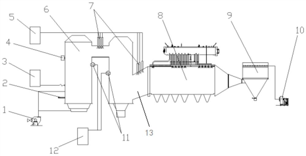
[0030] Specific implementation mode one: combine Figure 1 to Figure 2Specifically, this embodiment is a hazardous waste multi-phase co-processing device, which includes a blower 1, a feeder 2, a waste liquid tank 3, a high-pressure oxygen meter 4, an ammonia water tank 5, a multi-phase reactor 6, an ammonia water spray gun 7, Rapid cooling device 8, dust collector 9, induced draft fan 10, exhaust gas nozzle 11, exhaust gas tank 12 and second flue 13;

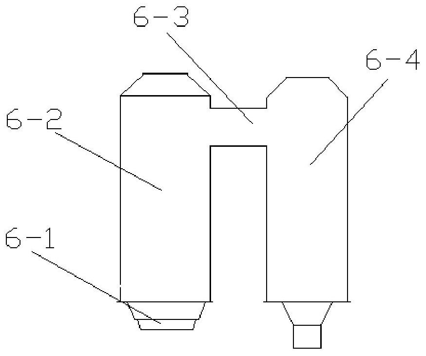
[0031] The multiphase reactor 6 is composed of an air chamber 6-1, a combustion chamber 6-2, a first flue 6-3 and a second combustion chamber 6-4; the combustion chamber 6-2 and the second combustion chamber 6 -4 are connected through the first flue 6-3, and the bottom of the combustion chamber 6-2 is provided with an air chamber 6-1; the combustion chamber 6-2 is provided with an air distribution plate;

[0032] The first flue 6-3 and the second flue 13 are provided with an ammonia spray gun 7, and the water inlet of the ammo...

specific Embodiment approach 2

[0044] Specific embodiment 2: The difference between this embodiment and specific embodiment 1 is that the exhaust gas inlets of the combustion chamber 6-2 and the second combustion chamber 6-4 communicate with the exhaust gas tank 12 through stainless steel pipes respectively; the combustion chamber The waste liquid injection port of 6-2 communicates with the waste liquid spray port of the waste liquid tank 3 through a stainless steel pipe. Others are the same as in the first embodiment.

specific Embodiment approach 3

[0045] Embodiment 3: This embodiment differs from Embodiment 1 or Embodiment 2 in that: the multiphase reactor 6 adopts an adiabatic furnace; the dust collector 9 is a bag filter. Others are the same as in the first or second embodiment.


PUM


Abstract

The invention discloses a hazardous waste multiphase cooperative treatment device and a hazardous waste treatment method thereof, and relates to a hazardous waste treatment device and a hazardous waste treatment method thereof. The problem that a large amount of acid gas and incompletely combusted organic components and furnace slag are generated by incineration of hazardous wastes in an existingincineration method is solved. The hazardous waste multiphase cooperative treatment device comprises an air blower, a feeding machine, a waste liquid tank, a high-pressure oxygen meter, an ammonia water tank, a multiphase reactor, an ammonia water spray gun, a rapid cooler, a dust remover, an induced draft fan, a waste gas spray head, a waste gas tank and a second flue. The process method comprises the steps that solid waste is placed on an air distribution plate of a combustion chamber, the air blower introduces air into the combustion chamber, and the waste liquid tank introduces waste liquid into the combustion chamber for combustion decomposition and waste gas burnout; primary removal is carried out on nitrogen oxide in the flue gas; and the rapid cooler is used for performing secondary denitration and absorbing the heat of the flue gas, then the dust remover is used for filtering particles in the flue gas, and the induced draft fan is used for leading out the flue gas to enter anacid making procedure.

Description

technical field [0001] The invention relates to a hazardous waste treatment device and a method for treating hazardous waste. Background technique [0002] With the development of industry, the hazardous waste discharged from industrial production process is increasing day by day. It is estimated that 330 million tons of hazardous waste are generated worldwide each year. Its hazards: 1 damage to the ecological environment. Hazardous waste discharged and stored randomly will pollute water bodies and soil under the long-term infiltration and diffusion of rainwater and groundwater, and reduce the environmental function level of the region. 2 affect human health. Hazardous wastes cause poisoning through ingestion, inhalation, skin absorption, eye contact, or dangerous events such as combustion and explosion; long-term hazards include long-term poisoning, carcinogenicity, teratogenicity, and mutagenesis caused by repeated exposure. 3 Restricting sustainable development. Poll...

Claims


Application Information

Patent Timeline
IPC IPC(8): F23G5/30F23G5/16F23G5/44F23G7/04F23J15/02F23J15/04F23J15/06F23L1/00
CPCF23G5/30F23G5/444F23G5/446F23G5/16F23G7/04F23L1/00F23J15/04F23J15/02F23J15/06F23J15/025F23J2215/10
Inventor 庞瑞朋徐亮翟冻冻
Owner 中晟工程技术(天津)有限公司
Why Eureka
Try Eureka