
A double-line drying combustion tower and its combustion method

A combustion tower and combustion zone technology, applied in the field of exhaust gas combustion equipment, can solve the problems of increased economic loss, harmful exhaust gas explosion, high operating cost, etc., and achieve the effects of sufficient combustion degree, longer time, and reduced emissions

Active Publication Date: 2018-05-01
FOLUNGWIN AUTOMATIC EQUIP CO LTD
View PDF6 Cites 0 Cited by
  • Summary
  • Abstract
  • Description
  • Claims
  • Application Information

AI Technical Summary

Problems solved by technology

The traditional equipment for dealing with these harmful gases mainly uses the method of burning flammable gases to burn harmful gases. The disadvantages of this method are: high operating costs, and harmful exhaust gases are prone to appear when flammable gases are extinguished or broken. There is a danger of explosion, and the production equipment must be shut down to overhaul the exhaust gas treatment equipment, which will undoubtedly increase economic losses

Method used


Image

  • A double-line drying combustion tower and its combustion method
  • A double-line drying combustion tower and its combustion method

Examples


Embodiment 1

[0036] Embodiment one: a kind of combustion method of double-line drying combustion tower, comprises the following steps:

[0037] A) Set the combustion cavity, and set a combustion cavity that can gradually burn the exhaust gas from bottom to top;

[0038] B) Set a combustion gas concentration cavity at the gas outflow position at the upper end of the combustion cavity;

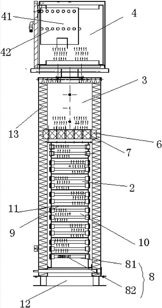
[0039] C) At the gas outlet position of the concentrated cavity, a cooling cavity that can cool the fully combusted gas and discharge it; the cooling cavity is equipped with a circulating water condenser; the cooling pipe of the circulating water condenser is S-shaped;

[0040] D) Multiple combustion zones are set in the combustion cavity of step A), and each combustion zone is arranged sequentially from bottom to top, and every two adjacent combustion zones are separated by a gas-permeable partition, and each gas-permeable partition A plurality of through-holes are arranged at intervals at one end of each; t...

Embodiment 2

[0042] Embodiment two: a kind of combustion method of double-line drying combustion tower, comprises the following steps:

[0043] A) Set the combustion cavity, and set a combustion cavity that can gradually burn the exhaust gas from bottom to top;

[0044] B) Set a combustion gas concentration cavity at the gas outflow position at the upper end of the combustion cavity;

[0045] C) At the gas outlet position of the concentrated cavity, a cooling cavity that can cool the fully combusted gas and discharge it; a circulating water condenser is installed in the cooling cavity; the cooling pipe of the circulating water condenser is U-shaped;

[0046] D) Multiple combustion zones are set in the combustion cavity of step A), and each combustion zone is arranged sequentially from bottom to top, and every two adjacent combustion zones are separated by a gas-permeable partition, and each gas-permeable partition A plurality of through-holes are arranged at intervals at one end of each; ...


PUM


Abstract

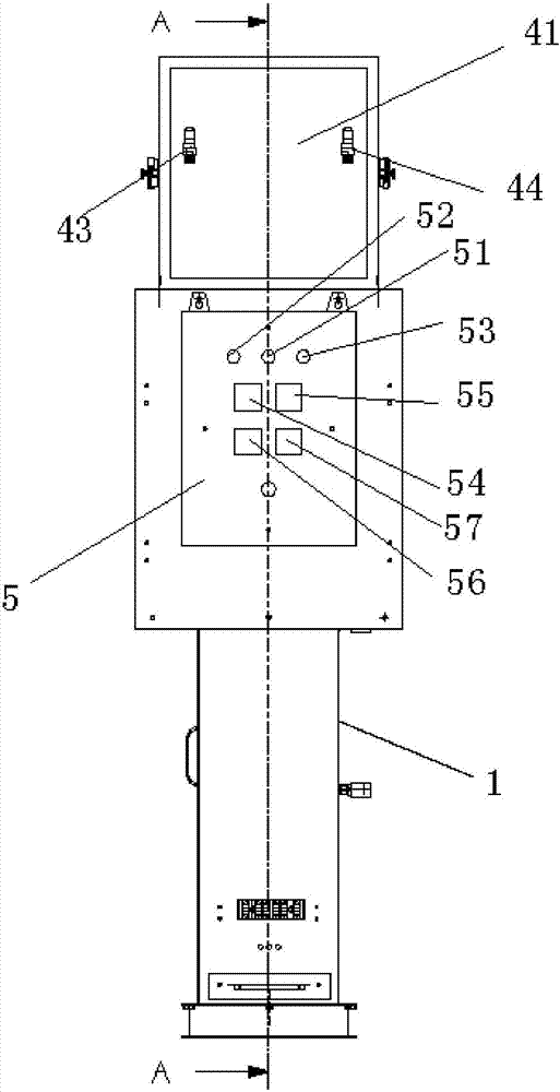
The invention discloses a double-wire drying combustion tower which comprises a combustion box body. A combustion cavity capable of prolonging the combustion time, a combustion gas gathering cavity used for gathering combustion gas and a cooling cavity used for cooling combusted gas are formed in a combusting cavity of the combustion box body in sequence from bottom to top. A control box used for controlling the temperature of the combustion box body is arranged on the front side or the rear side of the combustion box body. By means of the double-wire drying combustion tower and the combustion method thereof, a bottom-to-top layer-by-layer combustion manner is adopted, ventilation partition plates are arranged in a staggered manner, so that the time for waste gas particles to pass through each combustion area is prolonged, the waste gas particles can be combusted more sufficiently in each combustion area, and gas discharged afterwards reaches the marked discharging grade. By means of the combustion manner of the combustion tower, discharging of the waste gas particles can be greatly reduced, discharged gas can be more environment-friendly, all dust generated after combustion of the particles can be thoroughly removed through a dust collector, and collecting and cleaning of the combustion tower are facilitated.

Description

technical field [0001] The invention relates to waste gas combustion equipment, in particular to a double-line drying combustion tower. Background technique [0002] When using chemical vapor deposition (CVD) techniques in the solar cell manufacturing industry and in the manufacture of integrated circuits and electronic components, to prevent pollution and fire, it is necessary to avoid the release of used gases into the atmosphere and / or the production of these processes. gas. Certain gas compounds in these exhaust gases are toxic to humans, are flammable when in contact with air at high temperatures, and can spontaneously burn even when in contact with air or any oxidant at normal temperature. . The traditional equipment for dealing with these harmful gases mainly uses the method of burning flammable gases to burn harmful gases. The disadvantages of this method are: high operating costs, and harmful exhaust gases are prone to appear when flammable gases are extinguished ...

Claims


Application Information

Patent Timeline
Patent Type & Authority Patents(China)
IPC IPC(8): F23G7/06
CPCF23G7/063F23G2202/102F23G2204/20F23G2209/141
Inventor 苏金财冼志军王军涛
Owner FOLUNGWIN AUTOMATIC EQUIP CO LTD
Learn More