Supercharge Your Innovation With Domain-Expert AI Agents!

Gas combustion heat exchanger

A gas combustion and heat exchanger technology, applied in the direction of heat exchanger type, heat exchanger shell, indirect heat exchanger, etc., can solve the problems of insufficient heat exchange efficiency and large consumption of heat energy, etc. Heat transfer efficiency and overall height reduction effect

Pending Publication Date: 2020-05-19
黄思亮
View PDF0 Cites 0 Cited by
  • Summary
  • Abstract
  • Description
  • Claims
  • Application Information

AI Technical Summary

Problems solved by technology

[0002] Existing water heater heat exchangers are all coiled water pipes in the heat exchanger. When the gas is burned to exchange heat, it first heats the body, then transfers heat to the water pipes through heat transfer, and then heats the water through heat transfer. The thermal efficiency is not high enough and consumes a lot of heat energy

Method used


Image

  • Gas combustion heat exchanger
  • Gas combustion heat exchanger
  • Gas combustion heat exchanger

Examples


Embodiment 1

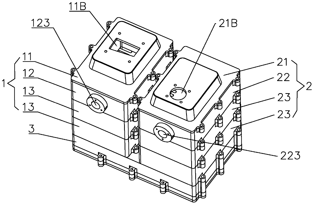
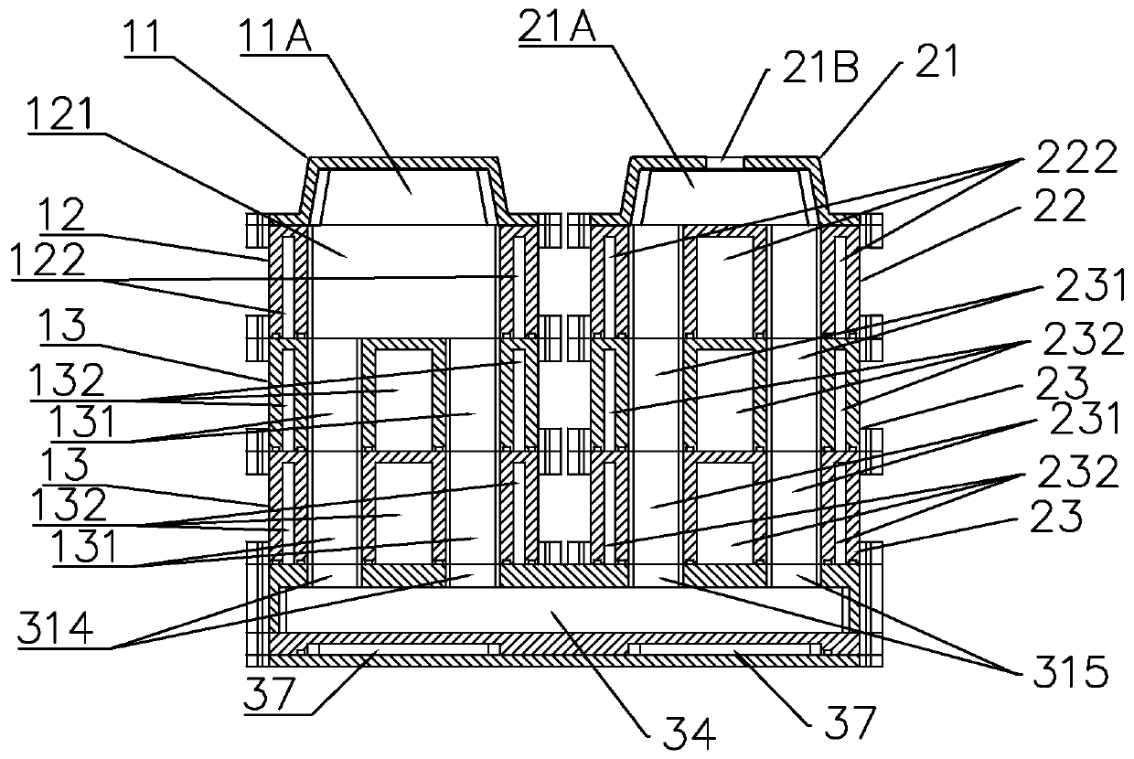
[0047] A gas combustion heat exchanger, the gas combustion heat exchanger is made of aluminum or copper; the gas combustion heat exchanger includes a left heat exchange body 1, a lower heat exchange body 3, a right heat exchange body 2, a left heat exchange body 1, a right The heat exchange body 2 is longitudinally fixed on the left and right ends of the lower heat exchange element 3. The upper inner part of the left heat exchange body 1 is provided with a combustion chamber 121, and the top of the combustion chamber 121 is provided with a burner installation through hole 11B. The right heat exchange body 2 The top of the top is provided with a smoke exhaust through hole 21B; the left heat exchange body 1, the lower heat exchange element 3, and the right heat exchange body 2 are provided with a total heat exchange channel 4 running through in a U-shaped trend in the middle of the three bodies. One end of the heat exchange channel 4 communicates with the burner installation thro...

Embodiment 2

[0049] A gas combustion heat exchanger, the gas combustion heat exchanger is made of aluminum; the gas combustion heat exchanger includes a left heat exchange body 1, a lower heat exchange element 3, and a right heat exchange body 2;

[0050] The left heat exchange body 1 includes a burner connection cover 11, a combustion chamber heat exchange element 12, and two general heat exchange elements 13, and the connections between them are all connected by sealing gaskets; the right heat exchange body 2 includes two Block general heat exchange part 2 23, water inlet heat exchange part 22, smoke exhaust cover 21, the connections between them are all connected by sealing gaskets;

[0051] The burner connection cover 11 is provided with a burner arrangement cavity 11A, and the top of the burner arrangement cavity 11A is a burner installation through hole 11B;

[0052] A combustion chamber 121 is provided in the longitudinal middle of the combustion chamber heat exchange element 12; a ...


PUM


Abstract

The invention discloses a gas combustion heat exchanger. A combustion cavity is formed in the inner upper portion of a left heat exchange body. A smoke discharge through hole is formed in the top of aright heat exchange body. A total heat exchange channel which runs in a U shape is formed in the left heat exchange body, the right heat exchange body and a lower heat exchange body. A sinuous totalwater channel is formed in the walls of the left heat exchange body, the right heat exchange body and the lower heat exchange body. After fire burns in a combustion chamber, flowing water is heated bythe heat of the fire through the total heat exchange channel; and cold water enters a water inlet, exchanges heat with the water channel to absorb heat, then turns into hot water and flows out of a water outlet in the other end. The height of the heat exchanger is reduced, the normal use heat exchange efficiency can be reached, and the overall height is reduced when the heat exchanger is installed in a water heater. The heat exchanger is an uncoiled water pipe, the sinuous water channel is directly arranged in the bodies of the heat exchanger, heat is directly transferred through the bodies of the heat exchanger to heat water, and the heat exchange efficiency is improved.

Description

technical field [0001] The invention relates to a water heater heat exchanger, in particular to a gas combustion heat exchanger. Background technique [0002] Existing water heater heat exchangers are all coiled water pipes in the heat exchanger. When the gas is burned to exchange heat, it first heats the body, then transfers heat to the water pipes through heat transfer, and then heats the water through heat transfer. The thermal efficiency is not high enough, and the heat energy consumption is large. Contents of the invention [0003] The technical problem to be solved by the present invention is to provide a coil-free water pipe, directly set the water channel in the heat exchanger body, heat the water directly through the heat exchanger body, improve the heat exchange efficiency, and the gas combustion heat exchange with the combined installation of components device. [0004] The solution to the above-mentioned technical problems is: [0005] A gas combustion heat ...

Claims


Application Information

Patent Timeline
IPC IPC(8): F28D7/08F28F9/04F28F9/22F28F9/24
CPCF28D7/08F28F9/04F28F9/22F28F9/24
Inventor 黄思亮
Owner 黄思亮
Features
  • R&D
  • Intellectual Property
  • Life Sciences
  • Materials
  • Tech Scout
  • Unparalleled Data Quality
  • Higher Quality Content
  • 60% Fewer Hallucinations
Learn More