
Thermosyphon heat dissipation device

A heat dissipation device and heat absorption and heat dissipation technology, which is applied in the direction of indirect heat exchangers, lighting and heating equipment, etc., can solve the problems of large disparity in heat absorption capacity of evaporators, etc., to facilitate pipeline layout, reduce pipe diameter, reduce The effect of space occupation

Pending Publication Date: 2020-05-19
SHENZHEN ZHIHAN THERMAL TRANSMISSION TECH CO LTD
View PDF0 Cites 2 Cited by
  • Summary
  • Abstract
  • Description
  • Claims
  • Application Information

AI Technical Summary

Problems solved by technology

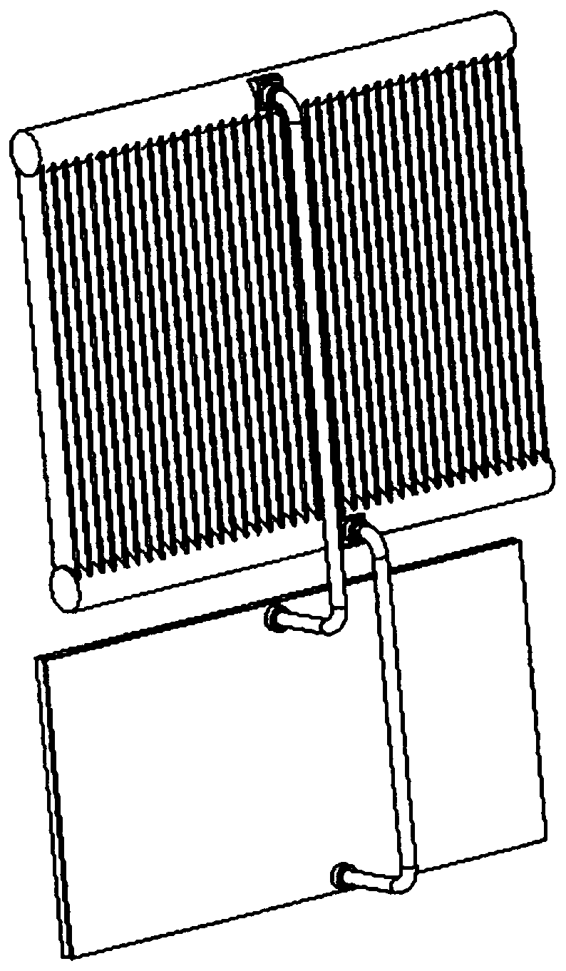
The steam pipe layout should be as short as possible to reduce the steam flow stroke, thereby reducing the steam flow resistance. In this arrangement, the steam pipe can only be connected to the side of the evaporator close to the header pipe used to collect steam. , then the steam on the side of the evaporator away from the header used to collect steam will have to flow a longer distance to reach the header, which will cause a large difference in heat absorption capacity between the left and right sides of the evaporator

Method used


Image

  • Thermosyphon heat dissipation device
  • Thermosyphon heat dissipation device
  • Thermosyphon heat dissipation device

Examples


Embodiment Construction

[0024] Typical embodiments that embody the features and advantages of the present invention will be described in detail in the following description. It should be understood that the present invention is capable of various changes in different embodiments without departing from the scope of the present invention, and that the description and illustrations therein are illustrative in nature and not limiting. this invention.

[0025] In the description of the present invention, it should be understood that the terms "above" and "below" refer to the azimuth relationship of the thermosyphon cooling device in use, in addition, other terms indicating orientation or positional relationship, such as "center ", "Portrait", "Landscape", "Length", "Width", "Thickness", "Front", "Back", "Left", "Right", "Vertical", "Horizontal", "Top" , "bottom", "inner", "outer", "clockwise", "counterclockwise", etc. are based on the orientation or positional relationship shown in the drawings, and are ...


PUM


Abstract

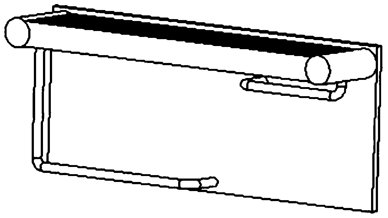
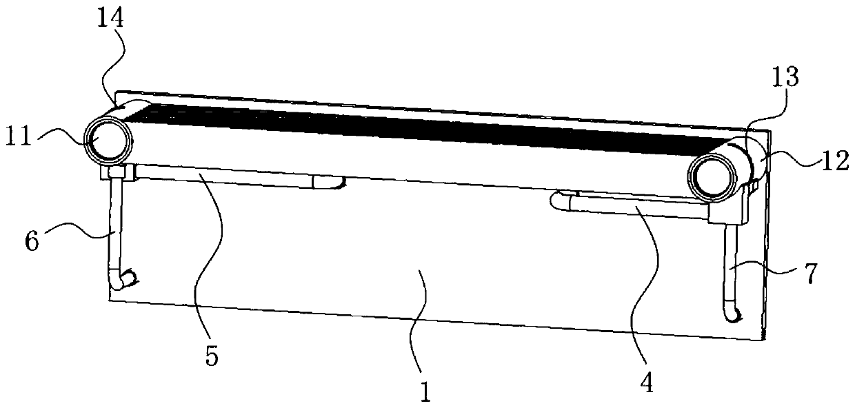
The invention provides a thermosyphon heat dissipation device. A first condensing unit and a second condensing unit are arranged, a first right flow collecting cavity and a first left flow collectingcavity of the first condensing unit and a second left flow collecting cavity and a second right flow collecting cavity of the second condensing unit are perpendicular to and fixedly arranged close toan evaporator, therefore, the space occupation of the thermosyphon heat dissipation device in the vertical direction is reduced; a first steam pipe communicates with the first right flow collecting cavity of the first condensing unit and a right steam pipe connecting hole formed in the evaporator, and a second steam pipe communicates with the second left flow collecting cavity of the second condensing unit and a left steam pipe connecting hole formed in the evaporator; and compared with the mode that only one flow collecting pipe used for collecting steam is arranged on one side of the evaporator, the technical scheme can reduce a stroke difference between the steam from the left side area and the steam in the right side area of a sealed containing cavity of the evaporator to the collecting cavities, and then the temperature difference between the left side and the right side of the evaporator is reduced, and the temperatures of the left and right sides of the bottom of the evaporatorare relatively uniform.

Description

technical field [0001] The invention relates to the technical field of heat dissipation of electronic or electric equipment, in particular to a thermosiphon heat dissipation device. Background technique [0002] The thermosiphon heat dissipation device is composed of a condenser, an evaporator, a steam pipe and a liquid pipe, etc. The evaporator is filled with a working fluid, and the condenser is usually composed of two collecting pipes on both sides and multiple pipes connecting the two liquid collecting pipes. The condensing tube is formed. The evaporator absorbs the heat from the heat source and the internal working medium heats up. The working medium heats up to generate steam. The steam enters the condenser through the steam tube to condense into a liquid with a lower temperature, and then flows back to the evaporator through the liquid tube, thereby realizing The heat dissipation effect on the heat source. [0003] In related schemes, refer to figure 1 , the condens...

Claims


Application Information

Patent Timeline
IPC IPC(8): F28D15/02
CPCF28D15/0266
Inventor 董陈
Owner SHENZHEN ZHIHAN THERMAL TRANSMISSION TECH CO LTD
Learn More