
Method for monitoring air particles and air abnormal components in switch cabinet

An abnormal composition, internal air technology, applied in particle suspension analysis, suspension and porous material analysis, measurement devices, etc. Infiltration of dust particles and other problems, to avoid insulation breakdown, avoid insulation flashover effect

Pending Publication Date: 2020-05-19
ELECTRIC POWER SCI & RES INST OF STATE GRID TIANJIN ELECTRIC POWER CO +2
View PDF9 Cites 4 Cited by
  • Summary
  • Abstract
  • Description
  • Claims
  • Application Information

AI Technical Summary

Problems solved by technology

However, through the analysis of switchgear defects and failure cases, it was found that dust and carbon accumulation in the switchgear caused insulation flashover, partial discharge defects caused insulation breakdown and other problems occurred frequently, and the problem could not be solved by means of heating or ventilation. Therefore, it is necessary to strengthen the switchgear. The monitoring of the operating environment inside the cabinet provides effective equipment operation information for operation maintenance and condition inspection, and avoids insulation flashover and insulation breakdown.
[0003] The causes of switchgear failures include the problem of dust and carbon accumulation in the switchgear and partial discharge problems. The main source of dust and carbon accumulation in the switchgear is dust particles in the air, which mainly enter through the ventilation system, heat dissipation net, and pressure relief channels. In the switchgear; it may also increase with the increase of the operating period, the poor sealing of the switchgear door will reduce the IP protection level, and the dust particles in the air will penetrate into the switchgear

Method used


Image

  • Method for monitoring air particles and air abnormal components in switch cabinet
  • Method for monitoring air particles and air abnormal components in switch cabinet
  • Method for monitoring air particles and air abnormal components in switch cabinet

Examples


Embodiment Construction

[0021] The present invention will be described in further detail below in conjunction with the accompanying drawings.

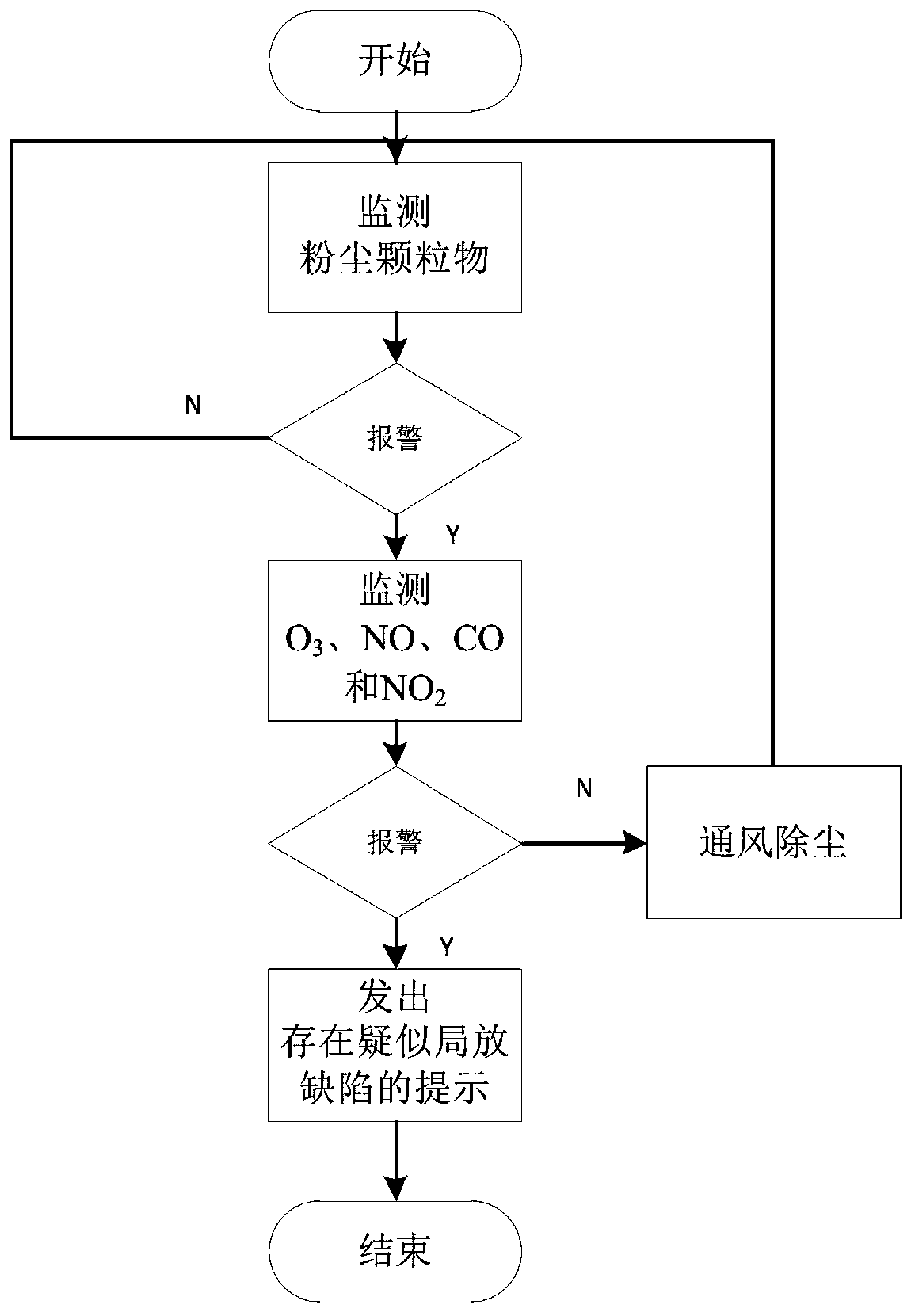
[0022] A method for monitoring air particles and abnormal air components inside a switchgear, such as image 3 shown, including the following steps:

[0023] Step 1. Monitor the dust particles inside the switchgear, and judge whether the concentration of dust particles reaches the alarm value. If it reaches the alarm value, alarm and go to step 2, otherwise go to step 5.

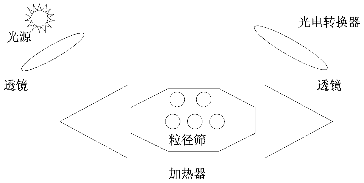
[0024] In this step, the infrared light scattering dust fall monitoring device using the particle calculation principle is used to monitor dust particles, and the infrared light scattering dust fall monitoring device is as follows: figure 1 As shown, it includes a particle size sieve, a light source, a heater, a light-transmitting mirror, and a photoelectric converter. The working process is as follows: the heater makes the dust particles generate a natural rising airflow through heating,...


PUM

PropertyMeasurementUnit
particle diameteraaaaaaaaaa

Abstract

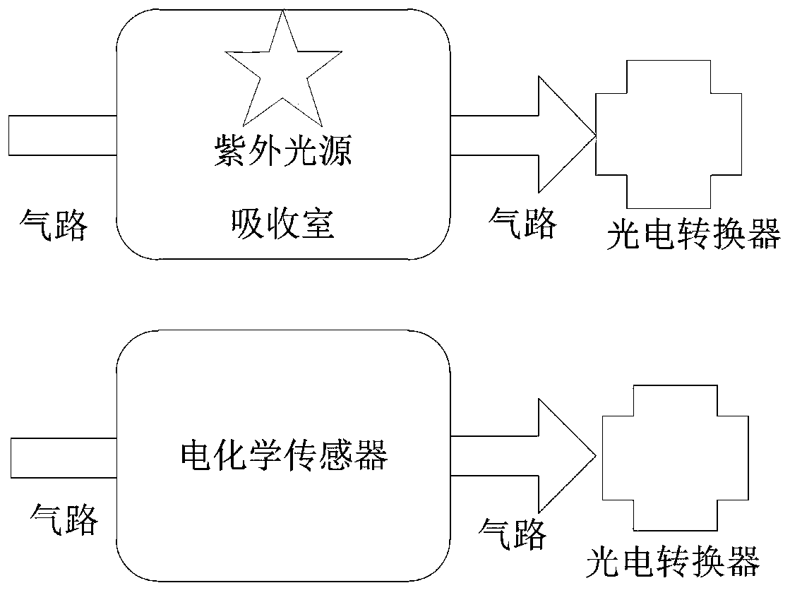
The invention relates to a method for monitoring air particles and air abnormal components in a switch cabinet. The method is characterized in that utilizing an infrared light scattering dust fall monitoring device adopting a particle calculation principle to monitor the concentration of dust particles, judging whether the alarm concentration is reached or not, if the alarm concentration is not reached, continuing to monitor, otherwise, monitoring the concentration of O3 by adopting an ultraviolet spectrum gas absorption principle, monitoring the concentrations of NO, CO and NO2 by adopting anelectrochemical principle, judging whether the alarm concentration is reached or not, if the alarm concentration is not reached, performing ventilation and dust removal, otherwise, sending out a prompt that the suspected partial discharge defect exists. The method is advantaged in that design is reasonable, monitoring of the internal operation environment of the switch cabinet is enhanced by monitoring abnormality of air particles and air components in the switch cabinet, the effective equipment operation condition information is provided for operation maintenance and state overhaul, and insulation flashover and insulation breakdown conditions are avoided.

Description

technical field [0001] The invention belongs to the field of high-voltage electrical appliances, in particular to a method for monitoring air particles and abnormal air components inside a switch cabinet. Background technique [0002] At present, the commonly used system for monitoring the internal operating environment of the switchgear is to control the heater power or ventilation by monitoring the temperature and humidity of the busbar room, circuit breaker room, and cable room of the temperature and humidity controller, so as to adjust the temperature and humidity inside the switchgear. the goal of. However, through the analysis of switchgear defects and failure cases, it was found that dust and carbon accumulation in the switchgear caused insulation flashover, partial discharge defects caused insulation breakdown and other problems occurred frequently, and the problem could not be solved by means of heating or ventilation. Therefore, it is necessary to strengthen the sw...

Claims


Application Information

Patent Timeline
Patent Type & Authority Applications(China)
IPC IPC(8): G01N15/06G01N21/33G01N27/26
CPCG01N15/06G01N21/33G01N27/26G01N15/075
Inventor 宋晓博陈荣张黎明何金朱旭亮邢向上
Owner ELECTRIC POWER SCI & RES INST OF STATE GRID TIANJIN ELECTRIC POWER CO
Learn More