
Discretized mold profile accurate compensation method

A mold surface and compensation method technology, which is applied in 3D modeling, design optimization/simulation, CAD numerical modeling, etc., can solve the problem that the point-to-point relationship between the mold surface and the part surface cannot be determined, the shape of the mold cannot be measured, and insufficient Accuracy and other issues, to achieve the effect of shortening the debugging cycle, saving the cost of mold testing, and improving accuracy and efficiency

Active Publication Date: 2020-05-19
SHANDONG UNIV
View PDF12 Cites 3 Cited by
  • Summary
  • Abstract
  • Description
  • Claims
  • Application Information

AI Technical Summary

Problems solved by technology

However, the inventors have found that most of the current research is only aimed at the springback of the part after it is released from the mold or only at the deformation of the mold during the forming process to compensate, or to complete the elastic deformation of the mold and the springback of the part for a certain section curve. Simultaneous compensation of springs, such as compensation of gear involutes, compensation of some sections of blades, etc., lack of reports on accurate compensation methods for space-complex profiles
This is due to the fact that it is difficult to use surface equations to describe complex profiles, and the research on multiple sections of the surface is not accurate enough, time-consuming, labor-intensive, and inefficient, and the shape of the mold after deformation and the shape of the part before springback cannot be obtained. Measurement, and the point-to-point relationship between the mold surface and the part surface cannot be determined, etc.

Method used


Image

  • Discretized mold profile accurate compensation method
  • Discretized mold profile accurate compensation method
  • Discretized mold profile accurate compensation method

Examples


Embodiment Construction

[0041] It should be pointed out that the following detailed description is exemplary and intended to provide further explanation to the present application. Unless defined otherwise, all technical and scientific terms used herein have the same meaning as commonly understood by one of ordinary skill in the art to which this application belongs.

[0042] It should be noted that the terminology used here is only for describing specific implementations, and is not intended to limit the exemplary implementations according to the present application. As used herein, unless the context clearly dictates otherwise, the singular is intended to include the plural, and it should also be understood that when the terms "comprising" and / or "comprising" are used in this specification, they mean There are features, steps, operations, means, components and / or combinations thereof.

[0043] As mentioned in the background technology, for relatively complex profiles, there are problems such as th...


PUM


Abstract

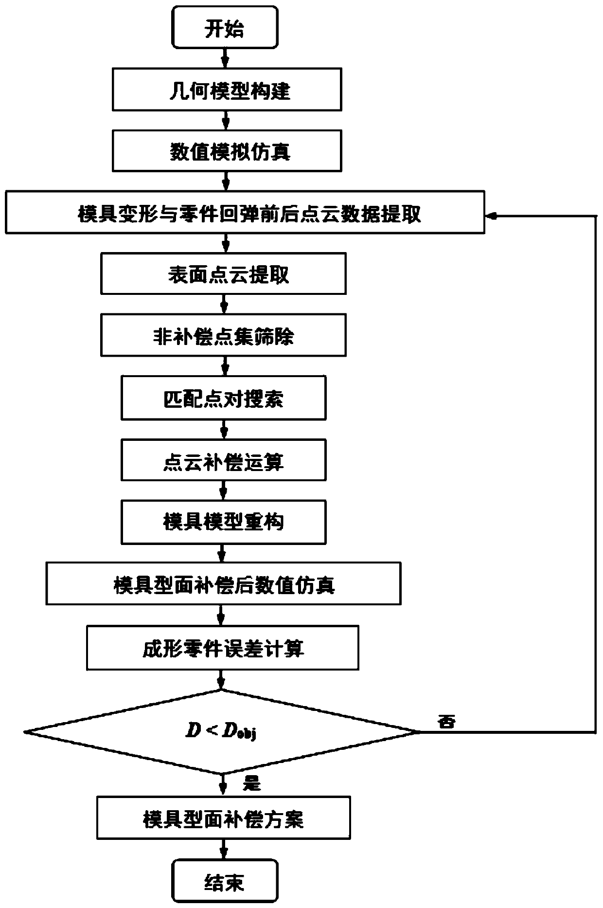
The invention belongs to the field of metal forging extrusion precision forming, in particular to a discretized mold profile accurate compensation method. The method is a profile compensation method based on point-to-point operation, analog simulation is carried out according to a novel profile of a mold after mold deformation and part springback compensation are completed by utilizing the method,and iterative compensation can be repeated if the forming precision does not meet the design requirement, so that accurate compensation for mold deformation and part springback is realized. The method is based on a profile reverse compensation principle; point cloud matching of the mold profile and the part profile is completed by utilizing a nearest point pair technical thought; therefore, all point clouds of the mold profile are compensated, the influence of mold deformation and part springback on the forming precision can be effectively reduced, meanwhile, the technology of directly generating the STL model through the point clouds is provided, point-line-surface fitting errors of a traditional profile are avoided, and the compensation precision of the complex mold profile is improved.The influence of mold deformation and part springback on the forming precision can be reasonably controlled, precise design of die products is facilitated, and the development efficiency is improved.

Description

technical field [0001] The invention belongs to the field of metal forging and extrusion precision forming, in particular to a numerical simulation-based compensation method for mold deformation and part springback. Background technique [0002] The information disclosed in the Background of the Invention is only intended to increase the understanding of the general background of the invention, and is not necessarily to be taken as an acknowledgment or any form of suggestion that the information constitutes the prior art that is already known to those skilled in the art. [0003] With the development of machinery industry, especially the continuous development of modern manufacturing industry, precision forging extrusion forming technology has been widely used. Using this technology, parts can meet their design requirements without subsequent processing or only a small amount of processing after forming. Therefore, The requirements for forming precision control are very high...

Claims


Application Information

Patent Timeline
IPC IPC(8): G06F30/20G06F30/17G06F111/10G06T17/10
CPCG06T17/10
Inventor 牟玥任否非陈云强赵国群王广春陈良
Owner SHANDONG UNIV
Learn More