110kV transformer substation main wiring structure using split transformer

A technology for splitting transformers and main wiring, applied in distribution substations, electrical components, circuit devices, etc., can solve the problems of increased investment, large operating loss, and complicated electrical wiring, etc., to increase the capacity of substations, improve power supply capacity, reduce The effect of engineering investment

Pending Publication Date: 2020-05-19
DONGGUAN ELECTRIC POWER DESIGN INST
View PDF0 Cites 3 Cited by
  • Summary
  • Abstract
  • Description
  • Claims
  • Application Information

AI Technical Summary

Problems solved by technology

[0003] The 20kV power distribution scheme is only applicable to a small number of newly planned areas. For the power supply areas covered by the 10kV power grid in the early stage, there is a lack of relevant planning and configuration, and most areas cannot be realized.
If you want to increase the power supply voltage level, you need to increase a lot of investment, which will cause a huge waste of resources
[0004] At present, the common 110kV / 10kV three-phase double-winding transformer capacity does not exceed 120MVA. To meet the needs of high loads, the power supply capacity of the 10kV side can only be increased by increasing the number of transformers or substations. This solution has electrical wiring Complexity, large project investment, large operating loss, large substation area, etc.
[0005] Compared with the common double-winding transformer, the three-phase double-winding split transformer has the advantages of large capacity, significant effect of limiting short-circuit current, and when one branch fails, the voltage drop of the busbar of the other branch is very small, etc., but it was rarely used in the past. In the substation as the main transformer

Method used


Image

  • 110kV transformer substation main wiring structure using split transformer
  • 110kV transformer substation main wiring structure using split transformer

Examples


Embodiment Construction

[0030] In order to facilitate the understanding of those skilled in the art, the present invention will be further described below in conjunction with the embodiments and accompanying drawings, and the contents mentioned in the embodiments are not intended to limit the present invention. The present invention will be described in detail below in conjunction with the accompanying drawings.

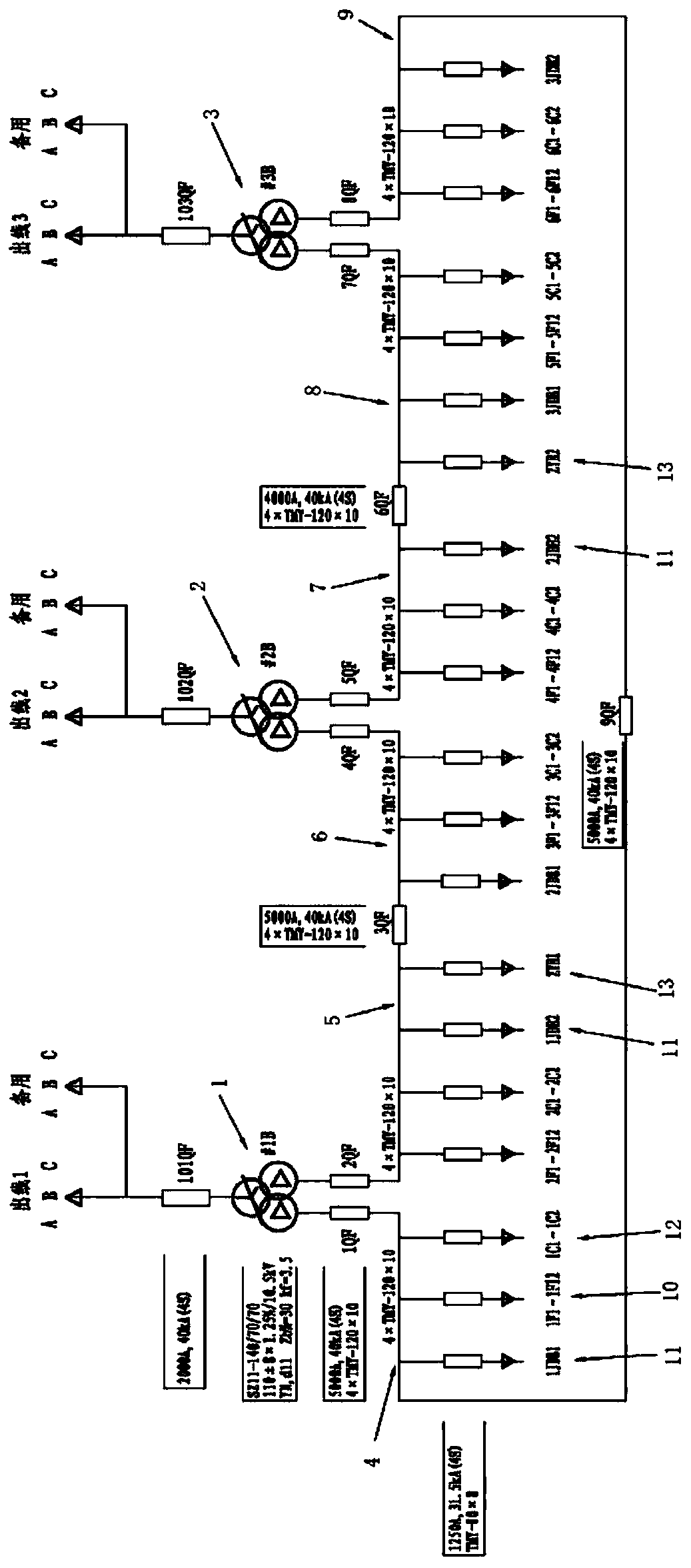
[0031] A main wiring structure of a 110kV substation using a split transformer, such as figure 1 As shown, including the first three-phase 110kV / 10kV double-winding split transformer 1, the second three-phase 110kV / 10kV double-winding split transformer 2 and the third three-phase 110kV / 10kV double-winding split transformer 3, the first three-phase 110kV The 110kV high-voltage winding side and the low-voltage winding side of the third three-phase 110kV / 10kV split-winding transformer 3 are respectively connected to 110kV power distribution equipment and 10kV power distribution device part; ...


PUM


Abstract

The invention relates to the technical field of power systems, and especially relates to a 110kV transformer substation main wiring structure using a split transformer. The 110kV transformer substation main wiring structure comprises a first three-phase 110kV / 10kV double-winding split transformer, a second three-phase 110kV / 10kV double-winding split transformer and a third three-phase 110kV / 10kV double-winding split transformer, wherein the 110kV high-voltage winding sides and low-voltage winding sides of the first three-phase 110 kV / 10 kV double-winding split transformer, the second three-phase 110kV / 10kV double-winding split transformer and the third three-phase 110kV / 10kV double-winding split transformer are respectively connected with a 110kV power distribution device part and a 10kV power distribution device part correspondingly. The capacity of the transformer substation is increased, and the electric energy requirement of a high-load-density region is met; and the structure hasthe characteristics of reducing engineering investment and ensuring safe and reliable operation of the substation.

Description

technical field [0001] The invention relates to the technical field of power systems, in particular to a main wiring structure of a 110kV substation using split transformers. Background technique [0002] With the rapid growth of national economy and electricity load, the load density of urban power grid is also increasing rapidly. Due to the continuous development of the city, the land use has become increasingly tight. Some areas plan to build substations according to the standard plan, and there are often problems such as too many projects and conflicts in the use of land resources. [0003] The adoption of 20kV power distribution scheme is only applicable to a small number of newly planned areas. For the power supply areas already covered by the previous 10kV power grid, there is a lack of relevant planning and configuration, and most areas cannot be realized. To increase the power supply voltage level, a large amount of investment is required, which will cause a huge w...

Claims


Application Information

Patent Timeline
Patent Type & Authority Applications(China)
IPC IPC(8): H02B1/22H02B7/06H02J3/00
CPCH02B1/22H02B7/06
Inventor 严勇涛吴启鹏王珍珠容文光王靖刘辉梁金强李泽宏黄文峰
Owner DONGGUAN ELECTRIC POWER DESIGN INST
Why Eureka
Try Eureka