
Frequency converter cabinet

A frequency converter and inverter technology, applied in the field of high-voltage frequency converters, can solve the time-consuming and laborious assembly of inverter components and circuit busbars, inconvenient disassembly of inverter components and circuit busbars, and reduce the service life of electric control components in frequency conversion cabinets and other issues to achieve the effects of saving assembly space, improving the efficiency of air in and out, and improving efficiency and stability

Pending Publication Date: 2020-05-19
QINGDAO CCS ELECTRIC CORP
View PDF0 Cites 2 Cited by
  • Summary
  • Abstract
  • Description
  • Claims
  • Application Information

AI Technical Summary

Problems solved by technology

[0003] Traditional inverter cabinets are generally equipped with a receiving plate for placing inverter components. In the existing technology, there is a problem of inconvenient connection in the connection of inverter components. The assembly of inverter components and circuit busbars is time-consuming and laborious. It is also inconvenient to disassemble the transformer components and circuit busbars
[0004] The inverter cabinet is installed inside the inverter component and the circuit busbar that cooperates with the inverter component. In the existing technology, there is a problem of uneven heat dissipation between the inverter component and the circuit busbar that cooperates with the inverter component. Long-term work leads to heat dissipation. The effect is poor, the frequency converter is unstable, and the work efficiency is affected
[0005] The top of the traditional inverter cabinet is equipped with an air outlet structure. The traditional air outlet structure has poor air outlet effect. The adjacent air outlets interfere with each other, resulting in poor air outlet effect and affecting the ventilation efficiency inside the inverter cabinet. The service life of the electric control components in the frequency conversion cabinet

Method used


Image

  • Frequency converter cabinet
  • Frequency converter cabinet
  • Frequency converter cabinet

Examples


Embodiment Construction

[0032] In the following, the present invention will be specifically described through exemplary embodiments. It should be understood, however, that elements, structures and characteristics of one embodiment may be beneficially incorporated in other embodiments without further recitation.

[0033] In the description of the present invention, it should be noted that the orientation or positional relationship indicated by the terms "inner", "outer", "upper", "lower", "front", "rear" etc. are based on the The positional relationship is only for the convenience of describing the present invention and simplifying the description, but does not indicate or imply that the referred device or element must have a specific orientation, be constructed and operated in a specific orientation, and thus should not be construed as limiting the present invention. In addition, the terms "first", "second", and "third" are used for descriptive purposes only, and should not be construed as indicating...


PUM


Abstract

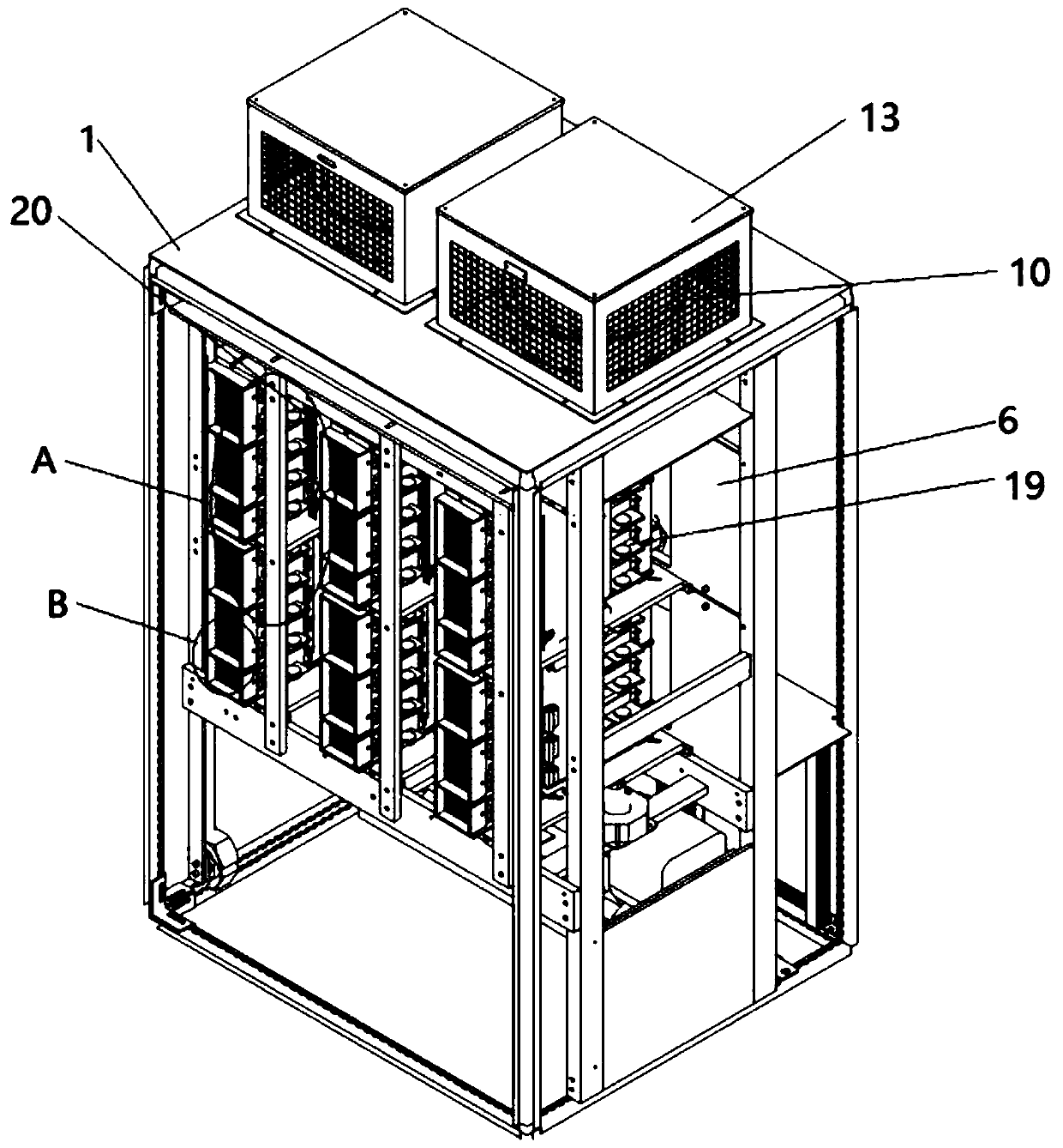
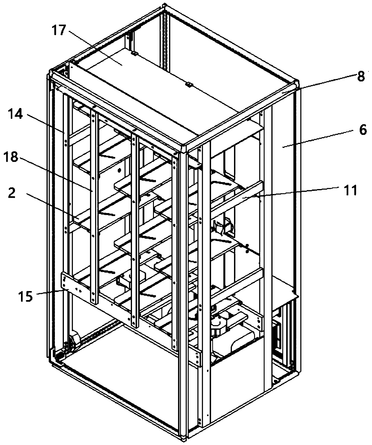
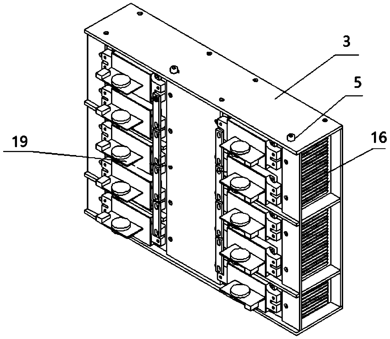
The invention relates to a frequency converter cabinet which comprises a supporting outer frame located in a frequency converter cabinet body, a supporting table connected to the supporting outer frame and a ventilation mechanism arranged on the frequency converter cabinet body. A fixing frame used for installing an inversion assembly is inserted on the supporting table. A sliding groove is formedin the supporting table. A protruding sliding block matched with the sliding groove in the supporting table is arranged on the inversion assembly fixing frame. The frequency converter cabinet has thebeneficial effects that the inversion assembly and a circuit busbar are convenient to disassemble, the inversion assembly and the circuit busbar matched with the inversion assembly are more uniform in heat dissipation, the heat dissipation effect is good, the frequency converter works stably, the working efficiency is improved, the air outlet effect is good, adjacent air blowing openings do not interfere with each other, and the service life of electric control elements in the frequency conversion cabinet is prolonged.

Description

technical field [0001] The invention belongs to the field of high-voltage frequency converters, and in particular relates to a frequency converter cabinet. Background technique [0002] Inverter is a power control device that converts power frequency power to another frequency by using the on-off function of power semiconductor devices. The electronic control components in the inverter include the inverter components and the circuit busbars that cooperate with the inverter components; Components realize various functions when the inverter is running, which is the guarantee for the stable, reliable and safe operation of the inverter. [0003] Traditional inverter cabinets are generally equipped with a receiving plate for placing inverter components. In the existing technology, there is a problem of inconvenient connection in the connection of inverter components. The assembly of inverter components and circuit busbars is time-consuming and laborious. There is also the proble...

Claims


Application Information

Patent Timeline
Patent Type & Authority Applications(China)
IPC IPC(8): H02M7/00H05K7/20
CPCH02M7/00H05K7/20909
Inventor 宋承林孙贤洲胡志勇赵彬
Owner QINGDAO CCS ELECTRIC CORP
Learn More