Planar diaphragm loudspeaker of magnetic reflux structure based on annular magnet

A technology of planar diaphragm and ring magnet, which is applied in the field of loudspeakers, can solve the problems of low production capacity and manufacturing efficiency, difficult to effectively reduce, thick and poor sense of density, etc., to improve dynamic control capabilities, reduce manufacturing costs, and improve sound production quality effect

Active Publication Date: 2020-05-19
杭州比值科技有限公司
View PDF13 Cites 0 Cited by
  • Summary
  • Abstract
  • Description
  • Claims
  • Application Information

AI Technical Summary

Problems solved by technology

Its advantages are: relatively easy to make, good linearity, small distortion, and wide frequency response; the disadvantage is: because the sounding diaphragm of the moving coil unit in the earphone is a cone-shaped structure, and when the power exceeds 60% during the sounding process, Due to the inherent limitations of the diaphragm shape and material, there is obvious distortion and the closer to the full load power, the distortion will increase exponentially, which will seriously deteriorate the sound
Its advantages are: long service life and high efficiency; disadvantages are: high price, large distortion, harsh high frequency, narrow frequency response, complex production process, high defect rate, often used in early telephone handsets
Due to the thinness of the diaphragm, the sound quality of electrostatic earphones is naturally light and transparent, and the performance of low frequency, sound thickness and density is slightly inferior; the disadvantage is that electrostatic earphones are mostly hand-made with a high defect rate and it is difficult to effectively reduce them. Production capacity and manufacturing efficiency are extremely low during manufacturing, and it is difficult to commercialize on a large scale, which is an insurmountable threshold
[0006] However, when the working power of the moving coil resolution exceeds 60%, the resolution begins to decline, and the sound is chaotic, and the greater the load, the more serious it is; the traditional dynamic speaker has been developed to the limit by the industry, and it is difficult to innovate with the acoustic logic such as physical structure. Upgrading; the acoustic characteristics of traditional dynamic speakers are difficult to upgrade with high quality in the original structure, and the cost for every improvement in sound quality will be several times or even more times, and the economy is very poor; the traditional dynamic speakers It is difficult for the diaphragm to be nano-scale thick, and it is difficult to greatly improve the sound quality. The sound with higher resolution has reached the limit.
In the actual manufacturing process of the planar diaphragm speaker structure, it is difficult to make the volume very small. Most of them are the volume of headphones, and it is impossible to achieve the in-ear earplug structure.
[0007] In addition, the magnets of existing planar diaphragm speakers are usually strip-shaped, resulting in relatively large volume of the manufactured earphones

Method used


Image

  • Planar diaphragm loudspeaker of magnetic reflux structure based on annular magnet
  • Planar diaphragm loudspeaker of magnetic reflux structure based on annular magnet
  • Planar diaphragm loudspeaker of magnetic reflux structure based on annular magnet

Examples


Embodiment 1

[0092] On the basis that the magnets on the ring and the magnets under the ring are arranged in a staggered manner, the sizes of the magnets on the ring and the magnets under the ring are exactly the same.

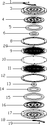
[0093] like figure 1 and figure 2 As shown, the upper magnet group includes two ring upper magnets, and the lower magnet group includes three ring lower magnets, wherein the ring upper magnets and the ring lower magnets are alternately arranged. A plurality of gaps are formed between the magnets on the adjacent rings, and the magnets under the rings are arranged facing the gaps.

[0094] (B) Asynchronous asymmetric formula:

[0095] On the basis of the staggered arrangement of the magnets on the ring and the magnets below the ring, the dimensions of the magnets on the ring and the magnets below the ring meet the following conditions:

[0096] The inner diameters of the magnets on the ring and the magnets under the ring are the same, and the outer diameters and heights ...

Embodiment 2

[0108] [Example 2] Peer-to-peer full alignment

[0109] The number of magnets on the ring is the same as that of the magnets under the ring, and on the basis of equal settings, the magnets on the ring and the magnets under the ring have exactly the same size.

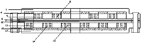
[0110] like Figure 4 and Figure 5 As shown, the upper magnet group includes 3 ring upper magnets, and the lower magnet group includes 3 ring lower magnets, and each ring upper magnet and ring lower magnet form a group, and each group of ring upper magnets and ring The centerlines of the vertical sections of the lower magnet lie on the same line. Moreover, the inner and outer diameters and heights of the magnets on each ring and the magnets below the ring are consistent.

Embodiment 3

[0111] [Example 3] Alignment within peers

[0112] The number of magnets on the ring and the magnets under the ring are different, and on the basis of equal settings, the magnets on the ring and the magnets under the ring are exactly the same in size.

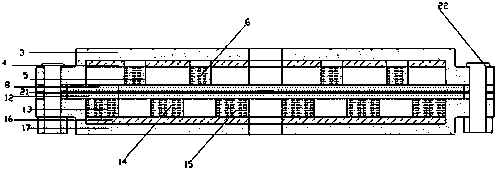
[0113] like Figure 7 and Figure 8 As shown, the upper magnet group includes: the third ring upper magnet 7 and the second ring upper magnet 6 from the inside to the outside, and the lower magnet group includes: the first ring lower magnet 13 from the inside to the outside, and the second ring lower magnet 6. Magnet 14 and magnet 15 under the third circular ring. Wherein, the magnet 7 on the third ring is set correspondingly with the magnet 13 under the first ring, the magnet 6 on the second ring is set correspondingly with the magnet 14 under the second ring, and the magnet 15 under the third ring has no corresponding ring On the magnet, the opposite is empty.


PUM


Abstract

The invention provides a planar diaphragm loudspeaker of a magnetic reflux structure based on an annular magnet, and the loudspeaker comprises an upper magnet supporting frame, and an upper magnet group is fixed at the inner side of the upper magnet supporting frame; a first supporting mechanism and a second supporting mechanism are arranged below the upper magnet set; a voice coil diaphragm mechanism is installed between the first supporting mechanism and the second supporting mechanism; a lower magnet supporting frame is further arranged below the second supporting mechanism; a lower magnetgroup is fixed on the inner side of the lower magnet support frame; a first external communication mechanism is arranged above the upper magnet support frame, a second external communication mechanismis arranged below the lower magnet support frame, the upper magnet group and the lower magnet group are oppositely arranged by taking the voice coil diaphragm mechanism as an interval, the upper magnet group comprises a plurality of circular ring upper magnets, and the lower magnet group comprises a plurality of circular ring lower magnets. According to the invention, the annular magnet structureis adopted; compared with an existing strip-shaped magnet structure, the produced earphone is smaller in size, and the sounding quality of the loudspeaker can be effectively improved.

Description

technical field [0001] The invention relates to the technical field of loudspeakers, in particular to a planar diaphragm loudspeaker with a magnetic return flow structure based on a ring magnet. Background technique [0002] Currently commonly used earphones are mainly divided into dynamic earphones, moving iron earphones and electrostatic (capacitive) earphones according to their different sounding principles. [0003] Dynamic earphones are the most common form of earphones today. It fixes the coil on the diaphragm and places it in a fixed magnetic field generated by a permanent magnet. The signal passes through the coil to cut the magnetic field lines, thereby driving the diaphragm to vibrate and produce sound together. Its advantages are: relatively easy to make, good linearity, small distortion, and wide frequency response; the disadvantage is: because the sounding diaphragm of the moving coil unit in the earphone is a cone-shaped structure, and when the power exceeds 60...

Claims


Application Information

Patent Timeline
IPC IPC(8): H04R9/02H04R9/06H04R9/04H04R7/04
CPCH04R9/02H04R9/06H04R7/04H04R9/04
Inventor 王洪宇王洪岩韩越王楠
Owner 杭州比值科技有限公司
Why Eureka
Try Eureka