Compatible with thyristor dimmer without flicker led drive circuit

A technology of LED driver and dimmer, applied in electrical components and other directions, can solve the problems of stroboscopic output and low efficiency, and achieve the effect of balanced input and output power and high efficiency

Active Publication Date: 2021-12-24
杭州欧佩捷科技有限公司
View PDF6 Cites 0 Cited by
  • Summary
  • Abstract
  • Description
  • Claims
  • Application Information

AI Technical Summary

Problems solved by technology

So that the existing linear thyristor dimming scheme existing in the compatibility of thyristor dimmer, low efficiency under high power factor requirements, output stroboscopic and other problems can be overcome

Method used


Image

  • Compatible with thyristor dimmer without flicker led drive circuit
  • Compatible with thyristor dimmer without flicker led drive circuit
  • Compatible with thyristor dimmer without flicker led drive circuit

Examples


Embodiment 1

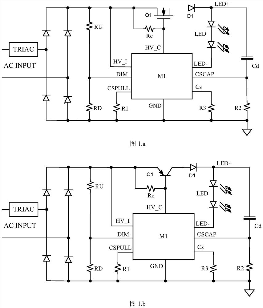
[0049] Embodiment 1. A non-flicker-free LED drive circuit compatible with thyristor dimmers, using a power MOS tube as an external power device Q1, such as figure 1 as shown in .a;

[0050] The flicker-free LED drive circuit compatible with thyristor dimmers includes a rectifier bridge, a functional block M1, an external power device Q1, an external ground-to-ground voltage divider network composed of resistors RU and RD connected in series, an isolation diode D1, and an electrolytic capacitor Cd. Charging current detecting resistor R2 (referred to as detecting resistor R2), LED load string, LED output current detecting resistor R3 (referred to as detecting resistor R3).

[0051] The mains power is supplied to the rectifier bridge through the thyristor dimmer TRIAC, the output voltage negative terminal of the rectifier bridge is connected to the ground, and the output voltage positive terminal of the rectifier bridge is respectively connected to the following components: an ex...

Embodiment 2

[0089] Embodiment 2, using a power PNP transistor as an external power device Q1 ( figure 1 .b)

[0090] The positive terminal of the output voltage of the rectifier bridge is respectively connected to the following components: an external voltage divider network composed of resistors RU and RD in series, the HV_I pin of the functional block M1, the HV_C pin of the functional block M1 after passing through the Rc resistor, and the external power device The emitter of Q1 ( figure 1 .b); The collector of the external power device Q1 is connected to the anode of the isolation diode D1;

[0091] The base of the external power device Q1 is connected to the HV_C pin of the functional block M1 and the Rc resistor;

[0092] The rest are equal to the above "a".

[0093] That is, compared with Embodiment 1 in Embodiment 2, Q1 is replaced by a PNP transistor instead of an N MOSFET in Embodiment 1. Due to the driving characteristics of the PNP transistor, the corresponding drive circu...


PUM


Abstract

The invention discloses a flicker-free LED drive circuit compatible with a thyristor dimmer, comprising a rectifier bridge, a functional block M1, an external power device Q1, an external ground-to-ground voltage divider network composed of resistors RU and RD connected in series, and an isolation diode D1, electrolytic capacitor Cd, charging current detection resistor R2, LED load string, LED output current detection resistor R3. The present invention ensures the corresponding input market when the thyristor dimmer is turned on by controlling and adjusting the turn-on voltage of the thyristor dimmer and the volt-second product of both ends of the corresponding thyristor dimmer. The instantaneous electrical voltage is greater than the voltage on the electrolytic capacitor, so that the thyristor dimmer can be turned on reliably.

Description

technical field [0001] The invention relates to an LED driving circuit, in particular to a non-stroboscopic LED driving circuit compatible with a thyristor dimmer. Background technique [0002] In order to make the output of the thyristor dimming LED drive circuit flicker-free, considering that there is no input power before the thyristor dimmer is turned on in phase cut, this requires an energy storage element to store energy to ensure that the thyristor dimming Before the optical device is tangentially turned on, the energy of the energy storage element provides a stable driving current to the LED load through the driving circuit. Usually this energy storage element is an electrolytic capacitor. How to ensure that the electrolytic capacitor can be charged by the commercial power through the thyristor dimmer within each half cycle is the focus of the present invention. [0003] For the electrolytic capacitor energy storage element, there are two requirements for the thyri...

Claims


Application Information

Patent Timeline
Patent Type & Authority Patents(China)
IPC IPC(8): H05B45/325H05B45/345H05B45/35H05B45/40
Inventor 翁大丰孙建中
Owner 杭州欧佩捷科技有限公司
Why Eureka
Try Eureka