Feed smashing equipment

A technology of crushing equipment and feed, applied in feed, cutting equipment, grain processing, etc., can solve the problem of single function and achieve the effect of convenient cutting

Inactive Publication Date: 2020-05-22
许冬梅
View PDF0 Cites 11 Cited by
  • Summary
  • Abstract
  • Description
  • Claims
  • Application Information

AI Technical Summary

Problems solved by technology

[0002] Feed crushing equipment is a commonly used equipment in the field of feed, but the general feed crushing equipment has a single function

Method used


Image

  • Feed smashing equipment
  • Feed smashing equipment
  • Feed smashing equipment

Examples


specific Embodiment approach 1

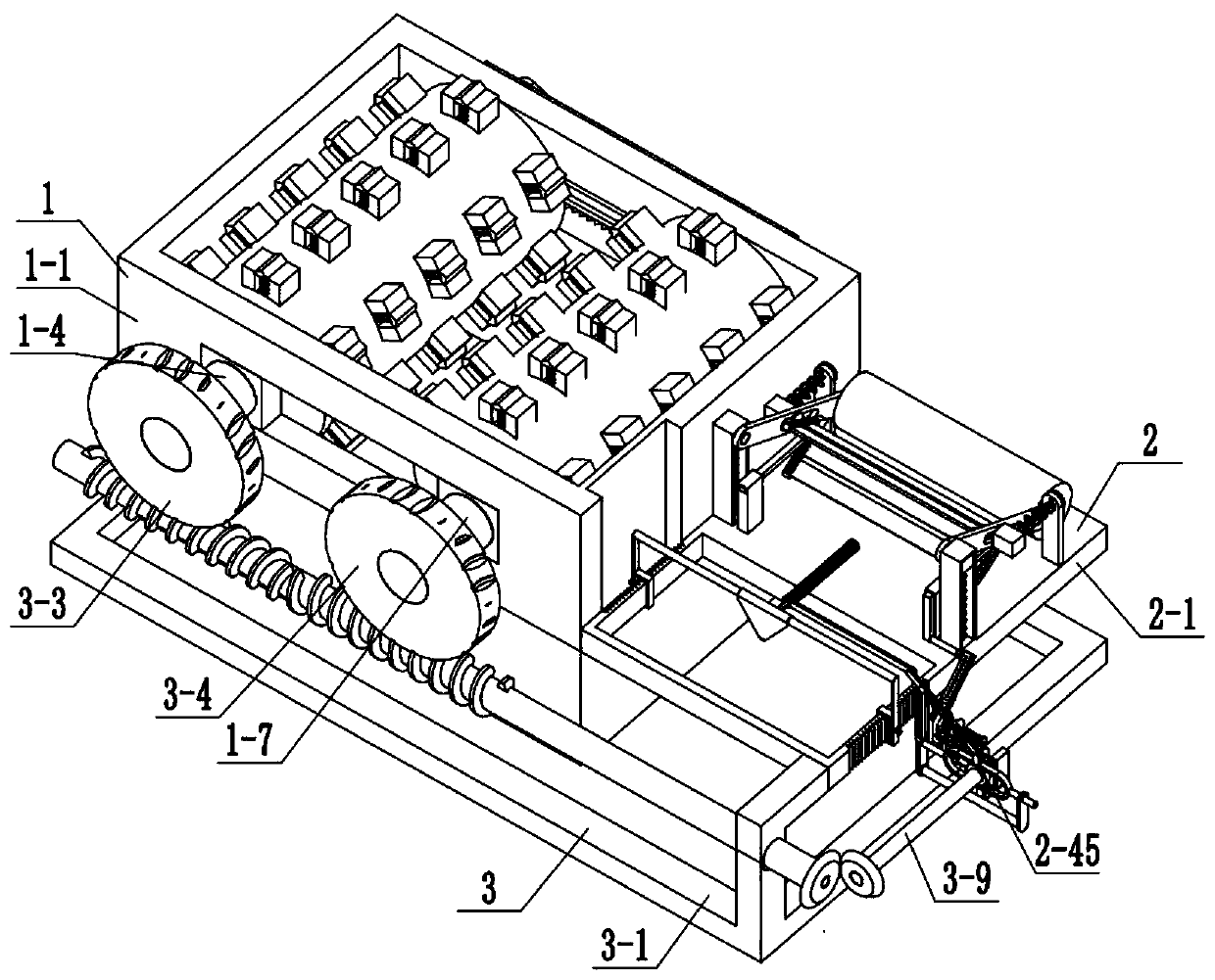
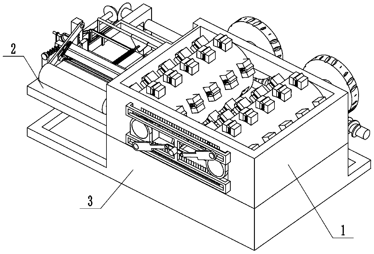
[0031] Combine below Figure 1-15 Describe this embodiment, a feed crushing equipment, including a crushing assembly 1, a cutting assembly 2, and a chassis assembly 3, the crushing assembly 1 is connected to the cutting assembly 2, and the bottom frame assembly 3 is connected to the cutting assembly Body 2 is connected.

specific Embodiment approach 2

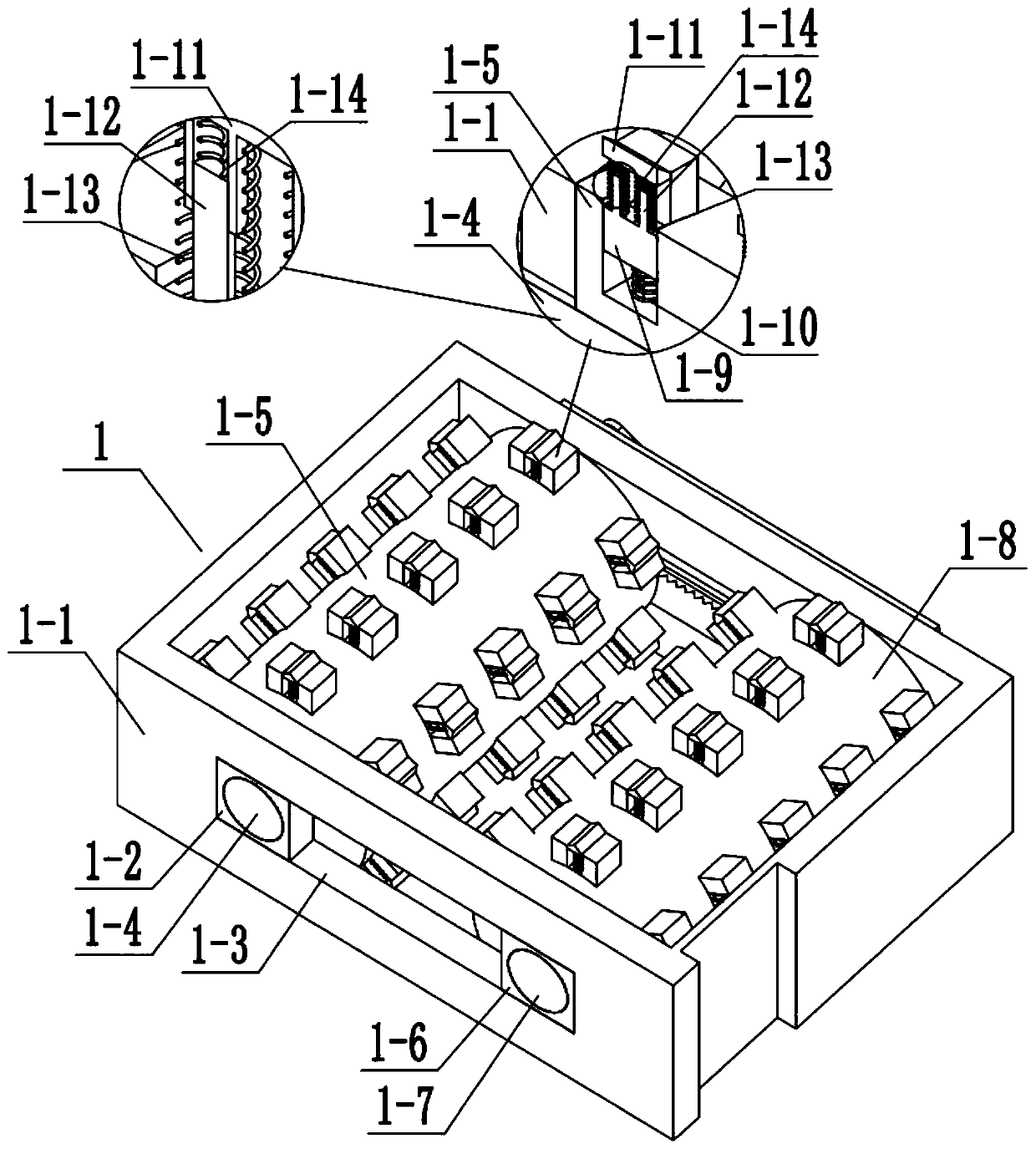
[0033] Combine below Figure 1-15 To illustrate this embodiment, the crushing assembly 1 includes a rectangular outer frame 1-1, a rectangular sliding frame 1-2, a rectangular chute 1-3, a rotating column 1-4, a crushing roller 1-5, a rectangular sliding frame Frame two 1-6, rotating column two 1-7, crushing roller two 1-8, vibrator slide rod one 1-9, vibrator push spring 1-10, crushing rod 1-11, inner end sliding column 1-12, inner End push spring one 1-13, inner end push spring two 1-14, rectangular limit frame 1-15, rectangular hollow groove 1-16, card slot 1-17, drive block 1-18, hinged rod 1-19, Middle-end rotating column 1-20, rectangular slider 1-21, inner end clamping rod 1-22, inner end spring 1-23, rectangular chute 1-3 is arranged on the rectangular outer frame 1-1, rectangular sliding Frame one 1-2 is slidingly connected with rectangular chute 1-3, rotating column one 1-4 is rotationally connected with rectangular sliding frame one 1-2, crushing roller one 1-5 is ...

specific Embodiment approach 3

[0035] Combine below Figure 1-15This embodiment will be described. This embodiment will further describe the first embodiment. The cutting assembly 2 includes a cutting frame 2-1, a side wall slot 2-2, an adjustable rectangular frame 2-3, and a cutting edge 2-4. , connecting sliding column 2-5, connecting sleeve spring 2-6, matching lever one 2-7, matching lever push spring 2-8, limiting outer frame 2-9, mid-end bracket one 2-10, bracket sliding Column one 2-11, middle bracket two 2-12, middle hinged frame one 2-13, middle bracket three 2-14, fixed connecting rod one 2-15, fixed connecting rod two 2-16, fixed connecting rod Three 2-17, fixed connecting rod four 2-18, fixed connecting rod five 2-19, fixed connecting rod six 2-20, fixed connecting rod seven 2-21, fixed connecting rod eight 2-22, fixed connecting rod nine 2 -23, rectangular sliding rod one 2-24, clamping rod one 2-25, clamping rod two 2-26, clamping rod sliding rod 2-27, clamping rod push spring 2-28, inner rec...


PUM


Abstract

The invention relates to the field of feed, in particular to feed smashing equipment. Mixture of soybean and bean cake can be smashed through a smashing and combining body; the smashing effect can beadjusted according to actual conditions; straw can be cut through a cutting and combining body; the cutting length of the straw can be adjusted according to actual conditions; and the machining speedof the device can be adjusted; the feed smashing equipment comprises the smashing and combining body, the cutting and combining body and a bottom frame and combining body, when a second bevel gear rotates, a first bevel gear is driven, then a middle-end rectangular frame is driven to move through an N-shaped frame, and through the action of a rectangular frame clamping groove and a driving inner sliding rod, a hinged connection block is driven and a driving rectangular rod is driven to move, then a first rectangular sliding rod is driven to slide along a second middle end support, then a firstclamping and moving rod and a second clamping and moving rod drive the straw to move forwards in a stepping mode along a cutting outer frame at the same time, straw transportation is completed, strawcutting is facilitated through a cutting blade, and straw pressing is achieved through a pressing roller.

Description

technical field [0001] The invention relates to the field of feed, in particular to a feed crushing equipment. Background technique [0002] Feed crushing equipment is a commonly used equipment in the field of feed, but the general feed crushing equipment has a single function. Contents of the invention [0003] The purpose of the present invention is to provide a kind of feed crushing equipment, which can crush the mixture of soybean and bean cake through the crushing assembly; and the effect of crushing can be adjusted according to the actual situation; the cutting of the straw can be realized by cutting the assembly; it can be adjusted according to the actual situation The cutting length of the straw; the processing speed of the device can be adjusted. [0004] The purpose of the present invention is achieved through the following technical solutions: [0005] A feed crushing equipment includes a crushing assembly, a cutting assembly, and a bottom frame assembly. The ...

Claims


Application Information

Patent Timeline
Patent Type & Authority Applications(China)
IPC IPC(8): B02C4/08B02C4/06B02C4/28B02C4/30B02C4/42A23N17/00A01F29/08A01F29/10
CPCA01F29/08A01F29/10A23N17/00A23N17/005B02C4/06B02C4/08B02C4/28B02C4/30B02C4/42
Inventor 许冬梅
Owner 许冬梅
Why Eureka
Try Eureka