High-safety cutting device for production of communication equipment shell

A technology of communication equipment and cutting device, applied in metal processing and other directions, can solve problems such as influence

Inactive Publication Date: 2020-05-22
钱丰
View PDF1 Cites 2 Cited by
  • Summary
  • Abstract
  • Description
  • Claims
  • Application Information

AI Technical Summary

Problems solved by technology

The device can well fix the raw material on the turntable, prevent it from shaking left and right during processing, improve the stability of the device, and drive the driving wheel to rotate, thereby adjusting the angle of the raw material on the turntable in conjunction with the toothed belt, and can push the fixed plate on the turntable. Sliding on the slide rail to adjust the position of the raw material, no manual operation, high degree of automation, avoiding the cumbersome procedures of manual operation, and safer, but the fixing device is located at the bottom of the device and will interfere with the cutting device, thus affecting the final The cutting process, so the device needs to be improved

Method used


Image

  • High-safety cutting device for production of communication equipment shell
  • High-safety cutting device for production of communication equipment shell
  • High-safety cutting device for production of communication equipment shell

Examples


Embodiment 1

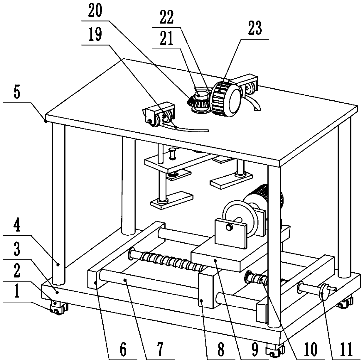
[0025] see Figure 1-3 , a cutting device with high safety for the production of communication equipment shells, comprising a bottom plate 3, spacers 2 are provided on the left and right sides of the lower surface of the bottom plate 3, casters 1 are provided on the lower part of the spacer 2, and the left and right sides of the upper surface of the bottom plate 3 have two sides. The side is provided with a support column 4, and the top of the support column 4 is provided with a top plate 5, and the middle part of the upper surface of the top plate 5 is provided with a second drive motor 23, and the output shaft of the second drive motor 23 is fixedly connected to the first bevel gear 22. A bevel gear 22 meshes with the second bevel gear 20, the second bevel gear 20 is fixedly connected to the upper end of the second main shaft 21, the middle part of the second main shaft 21 is rotatably connected to the middle part of the top plate 5, and the lower end of the second main shaft...

Embodiment 2

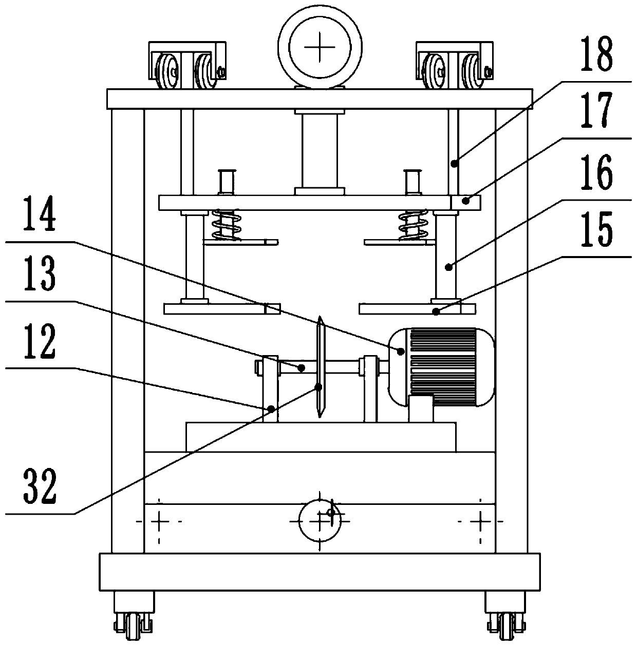
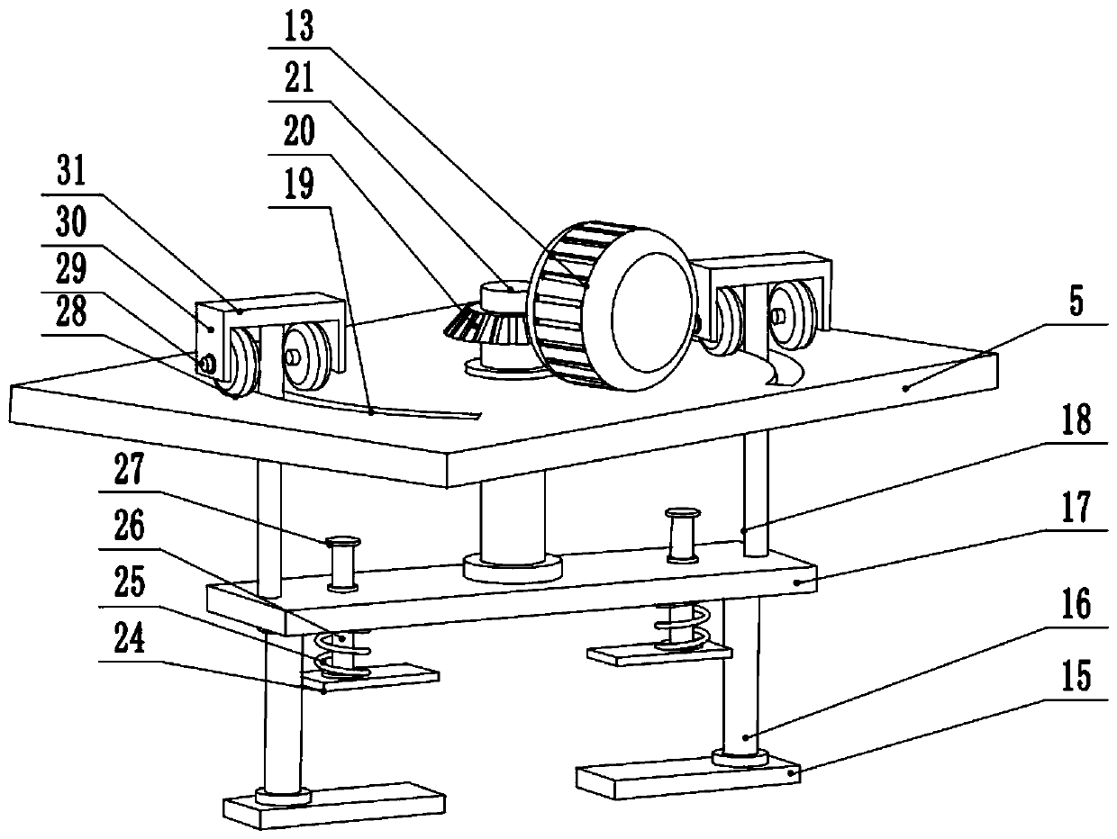
[0028] see figure 1 , the other content of this embodiment is the same as that of Embodiment 1, except that the upper end of the second support rod 18 is connected to the middle of the lower surface of the third mounting plate 31, and the front and rear sides of the lower surface of the third mounting plate 31 are provided with Side plate 30 is arranged, and the bottom of side plate 30 is rotatably connected with turning bar 29 , and the end of turning bar 29 is provided with supporting wheel 28 . Because the second mounting plate 17 bears the weight of the entire shell and the clamping part, in order to ensure the stability during cutting, a support wheel 28 is set on the upper end of the second support rod 18, and the weight of the clamping device is supported by the support wheel 28. Therefore, the influence of the entire clamping part on the second main shaft 21 is reduced, the strength requirement for the second main shaft 21 is reduced, and the stability of the entire de...


PUM


Abstract

The invention relates to the technical field of communication equipment, and discloses a high-safety cutting device for production of a communication equipment shell. The high-safety cutting device comprises a bottom plate, supporting columns are arranged on the left side and the right side of the upper surface of the bottom plate, a top plate is arranged at the tops of the supporting columns, a second driving motor is arranged in the middle of the upper surface of the top plate, a first bevel gear is fixedly connected to an output shaft of the second driving motor, the first bevel gear is inengaged connection with a second bevel gear, the second bevel gear is fixedly connected with the upper end of a second main shaft, the lower end of the second main shaft is fixedly connected with a second mounting plate, first supporting rods are arranged at the front end and the rear end of the lower surface of the second mounting plate, lower clamping plates are arranged at the lower ends of thefirst supporting rods, and the front side and the rear side of the second mounting plate are slidably connected with second guiding rods. According to the high-safety cutting device for production ofthe communication equipment shell, in the overall cutting process, upper clamping plates and the lower clamping plates do not affect moving of cutting wheels, and thus the cutting effect is ensured.

Description

technical field [0001] The invention relates to the technical field of communication equipment, in particular to a high-safety cutting device for the production of communication equipment shells. Background technique [0002] Communication has different interpretations in different environments. After the emergence of radio wave transmission communication, communication is singlely interpreted as the transmission of information, which refers to the transmission and exchange of information from one place to another. The purpose is to transmit messages. However, Communication is in the process of human practice. With the development of social productive forces, the requirements for message transmission are constantly improving, which makes human civilization continue to progress. Among various communication methods, the communication method that uses "electricity" to transmit messages is called telecommunications. Nowadays, communication is generally realized through signal tr...

Claims


Application Information

Patent Timeline
Patent Type & Authority Applications(China)
IPC IPC(8): B26D1/16B26D5/08B26D5/02B26D7/02B26D7/00
CPCB26D1/16B26D5/02B26D5/086B26D7/00B26D7/02
Inventor 钱丰
Owner 钱丰
Why Eureka
Try Eureka