Glazing device for strung spoons

The technology of string spoon and transmission device is applied in the field of string spoon glazing device, which can solve the problems of long soaking time, insufficient soaking time to affect the effect of ceramic spoon glazing, inability to soak ceramic spoon, etc., so as to achieve the effect of convenient glazing.

Active Publication Date: 2020-05-22
梁泽冲
View PDF6 Cites 4 Cited by
  • Summary
  • Abstract
  • Description
  • Claims
  • Application Information

AI Technical Summary

Problems solved by technology

[0005] In order to overcome the disadvantages of complex operation and long soaking time in the traditional method, many ceramic spoons cannot be soaked at the same time, and the soaking time is not enough to affect the effect of glazing ceramic spoons. The technical problem of the present invention is to provide a method for glazing ceramic spoons Simple and capable of controlling the soaking time of ceramic spoons in dye

Method used


Image

  • Glazing device for strung spoons
  • Glazing device for strung spoons
  • Glazing device for strung spoons

Examples


Embodiment 1

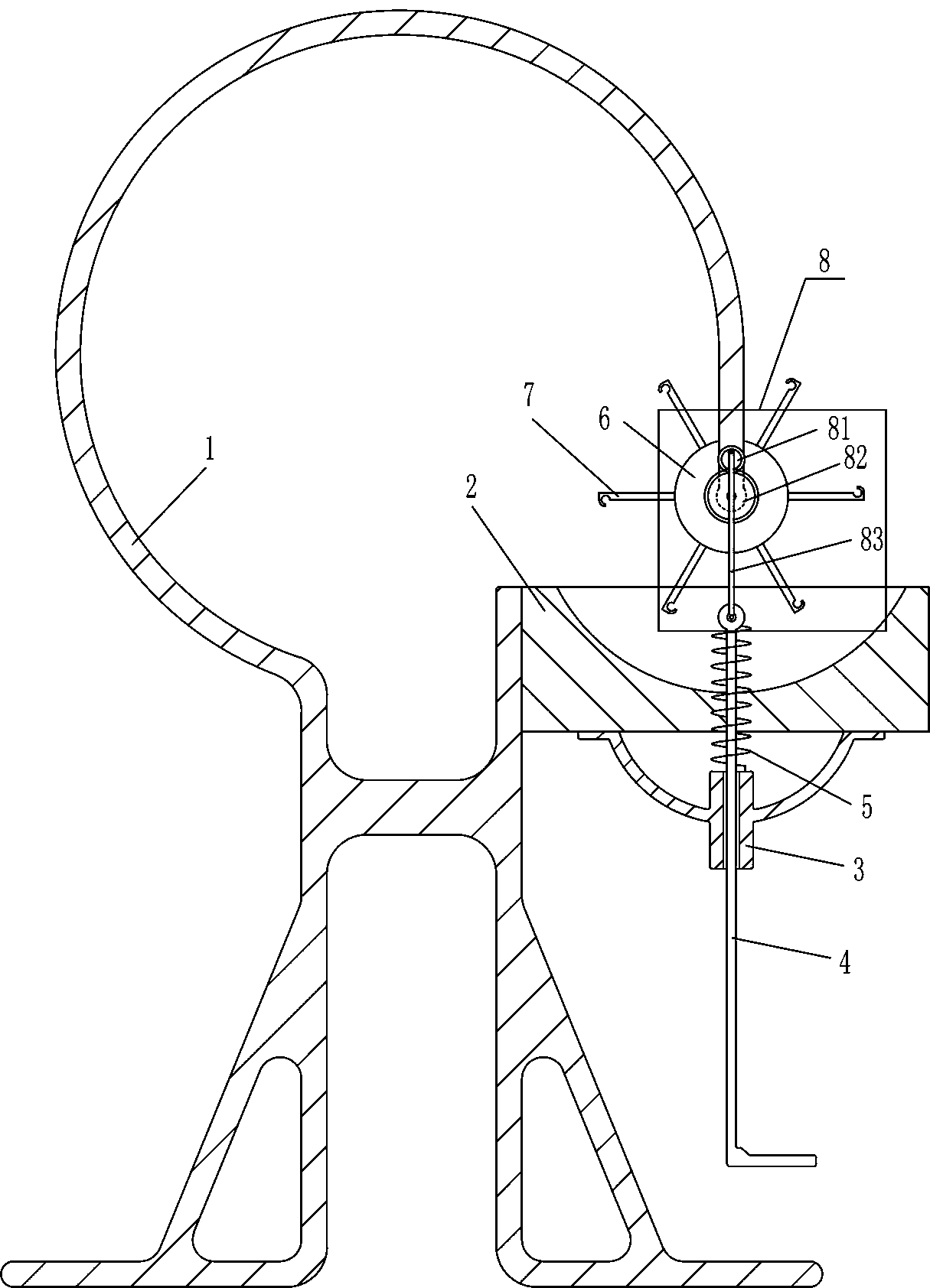
[0019] A skewer glazing device, such as figure 1 As shown, it includes a bracket 1, a material storage box 2, a first sliding sleeve 3, a pedal 4, a return spring 5, a turntable 6, a hook 7 and a transmission device 8, and the right side of the middle part of the bracket 1 is fixedly connected with a material storage box 2, The bottom of the material storage box 2 is fixedly connected with a first sliding sleeve 3, and a pedal 4 is slidably connected in the first sliding sleeve 3. The upper part of the pedal 4 is covered with a return spring 5, and the two ends of the return spring 5 are connected with the first sliding sleeve respectively. The upper part of 3 is fixedly connected with the upper part of pedal 4, and the rear side of the right part of support 1 is rotatably connected with turntable 6, and the outside of turntable 6 has ring arrays 7 in front and rear, and the front side of turntable 6 is connected with transmission device 8, pedal 4 The top of the top is connec...

Embodiment 2

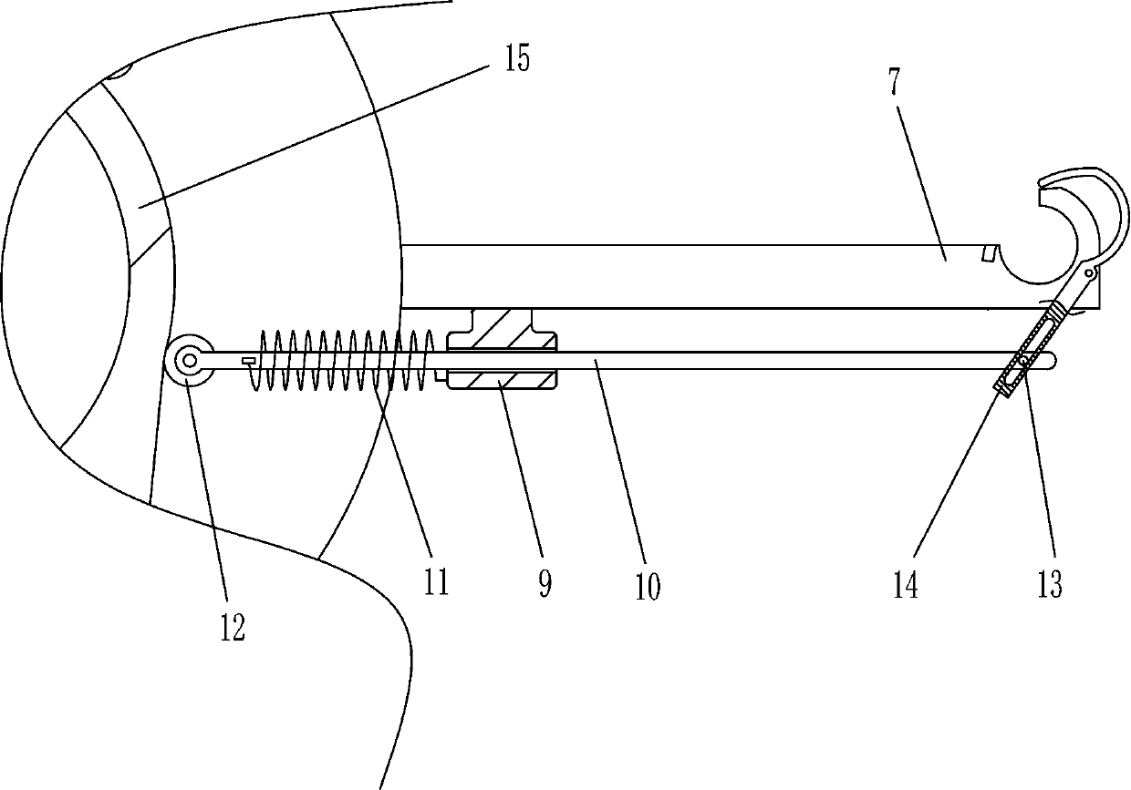
[0024] On the basis of Example 1, such as figure 2 Shown, also include fixing mechanism and cam 15, the bottom of each hook 7 is all provided with fixing mechanism, the right part of support 1 is fixedly connected with cam 15, and cam 15 is the same circle center position with rotating disk 6, and fixing mechanism includes the first Two sliding sleeves 9, the first sliding bar 10, the first spring 11, the first roller 12, the pin bar 13 and the swing bar 14, the bottom of each hook 7 is fixedly connected with the second sliding sleeve 9, the second sliding sleeve 9 The inner sliding type is connected with the first slide bar 10, and the inner end of the first slide bar 10 is covered with the first spring 11, and the two ends of the first spring 11 are connected with one side of the second slide sleeve 9 and the first slide bar 10 respectively. The inner end is fixedly connected, the inner end of the first slide bar 10 is rotatably connected with the first roller 12, the outer...

Embodiment 3

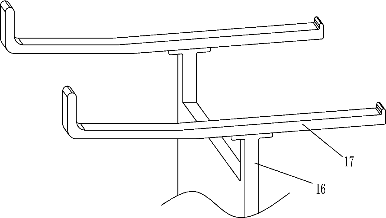
[0027] On the basis of Example 2, such as Figure 3-4 As shown, it also includes a second slide bar 16, a support plate 17, a second spring 18, a second roller 19 and a first bump 20, and the middle part of the bracket 1 is slidably connected with the second slide bar 16, and the second slide bar The front and rear ends of the top of 16 are fixedly connected with support plates 17, and the right part of the second slide bar 16 is covered with a second spring 18, and the left and right ends of the second spring 18 are connected with the right side of the support 1 and the second slide bar 16 respectively. The right part is fixedly connected, and the rear right part of the second slide bar 16 is rotatably connected with a second roller 19 , and the left side of the pedal 4 is fixedly connected with a first lug 20 , and the first lug 20 is in contact with the second roller 19 .

[0028]When the ceramic spoon is glazed, the pedal 4 moves down and squeezes the second roller 19 thro...


PUM


Abstract

The invention relates to a glazing device, in particular to a glazing device for strung spoons. According to the glazing device for the strung spoons, the glazing operation of ceramic spoons is simple, and the soaking time of the ceramic spoons in dye can be controlled. The glazing device for the strung spoons comprises a support, a storage box and the like; and the storage box is fixedly connected with the right side of the middle of the support. According to the glazing device, the ceramic spoons on a rotating disc is driven to rotate by adopting a pedal mode, the ceramic spoons can be rotated into the storage box, and the ceramic spoons are covered with coating, so that the glazing function on the ceramic spoons is completed; and a first slide bar is extruded through the protruding partof a cam, the ceramic spoons on hooks are fixed with a swinging rod, and the placed ceramic spoons fall into the storage box, so that the ceramic spoons are glazed more conveniently.

Description

technical field [0001] The invention relates to a glazing device, in particular to a string ladle glazing device. Background technique [0002] When making ceramic spoons, the spoon needs to be glazed. Glaze is a colorless or colored glassy thin layer covering the surface of ceramic products. It is made of feldspar, quartz, talc, kaolin and other mineral materials in a certain proportion. It is made into glaze slurry after being ground, soaked in the surface of the body and calcined at a certain temperature, which can increase the mechanical strength and thermal stability of the product, and also has the characteristics of beautifying the utensils, being easy to wipe and cleaning, and not being corroded by dust and filth. [0003] The traditional glazing method is to manually string the ceramic spoon on a pole, and then put the ceramic spoon on the pole into the dye through the hook, soak for a while, and then lift it up to shake off the dye on the ceramic spoon , because t...

Claims


Application Information

Patent Timeline
Patent Type & Authority Applications(China)
IPC IPC(8): B28B11/04
CPCB28B11/044
Inventor 梁泽冲
Owner 梁泽冲
Why Eureka
Try Eureka