
Synchronous belt forming device

A molding equipment and synchronous belt technology, applied in the field of CNC machine tools, can solve the problems of occupying space, low production efficiency and poor stability of the synchronous belt molding machine, and achieve the effects of good stability, high yield and high production efficiency

Pending Publication Date: 2020-05-22
TAIZHOU CHIJUN INTELLIGENT EQUIP CO LTD +1
View PDF0 Cites 0 Cited by
  • Summary
  • Abstract
  • Description
  • Claims
  • Application Information

AI Technical Summary

Problems solved by technology

[0003] In the prior art, synchronous belt molding machines have disadvantages such as low production efficiency, poor stability, and space occupation

Method used

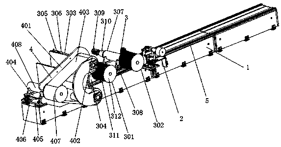

Image

  • Synchronous belt forming device
  • Synchronous belt forming device

Examples


Embodiment Construction

[0016] The present invention will be further explained below in conjunction with the accompanying drawings and embodiments.

[0017] Such as Figure 1-Figure 2 As shown, a synchronous belt forming equipment includes a frame 1, a steel wire winding mechanism 2, a steel wire output mechanism 3 and a steel belt extrusion forming mechanism 4, and the frame 1 is provided with a linear guide rail 5, and the steel wire is wound The wire device 2, the steel wire output mechanism 3 and the steel strip extrusion forming mechanism 4 are sequentially arranged on the linear guide rail 5;

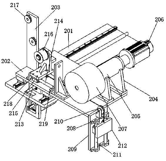
[0018] The wire winding mechanism 2 includes a first base plate 201, a second base plate 202, a reversing wheel mounting plate 203, a first headstock base 204, a first headstock 205, a first servo motor 206, a steel wire cylinder 207 and a A counterweight mechanism 208 with steel wire tightened, the counterweight mechanism 208 includes a support vertical plate 209, a reversing pulley 210, a first light ...


PUM


Abstract

The invention discloses a synchronous belt forming device. The synchronous belt forming device comprises a rack (1), a steel wire winding mechanism (2), a steel wire output mechanism (3) and a steel belt extrusion forming mechanism (4), wherein the rack (1) is provided with a linear guide rail (5), and the steel wire winding mechanism (2), the steel wire output mechanism (3) and the steel belt extrusion forming mechanism (4) are arranged on the linear guide rail (5) in sequence; and the steel wire winding mechanism (2) comprises a first bottom plate (201), a second bottom plate (202), a reverse wheel installation plate (203), a first spindle box base (204), a first spindle box (205), a first servo motor (206), a steel wire cylinder (207) and a balance weight mechanism (208) which is used for tightening a steel wire up. The synchronous belt forming device is high in production efficiency, high in running stability and high in yield.

Description

technical field [0001] The invention relates to the technical field of numerical control machine tools, in particular to a synchronous belt forming device. Background technique [0002] At present, the synchronous belt uses a steel wire rope as a strong layer and is covered with a polyurethane or neoprene endless belt. It combines the advantages of belt transmission, chain transmission and synchronous belt transmission. To transmit power, so the transmission ratio is accurate, the force on the shaft is small, the structure is compact, and the synchronous belt is oil-resistant, wear-resistant, and anti-aging performance is good, a constant speed ratio can be obtained, the transmission is stable, vibration absorption and noise are small, and the transmission ratio It has a wide range and is widely used in various transmission machinery. In the production process of the timing belt, it is generally made by a timing belt molding machine, including the process of arranging the w...

Claims


Application Information

Patent Timeline
Patent Type & Authority Applications(China)
IPC IPC(8): B29C43/28B29C43/48B29C43/32B29C43/58
CPCB29C43/28B29C43/32B29C43/48B29C43/58B29C2043/486
Inventor 陈群李卫民施华林李曙生徐洪伟于雯
Owner TAIZHOU CHIJUN INTELLIGENT EQUIP CO LTD
Learn More