
High-low pressure lubricating system for high power plunger pump

A lubrication system and plunger pump technology, applied in the field of plunger pump lubrication, to avoid uneven distribution, improve utilization, and improve service life

Pending Publication Date: 2020-05-22
美国杰瑞国际有限公司
View PDF9 Cites 97 Cited by
  • Summary
  • Abstract
  • Description
  • Claims
  • Application Information

AI Technical Summary

Problems solved by technology

[0003] The purpose of the present invention overcomes the deficiencies of the prior art, and provides a high-low pressure lubrication system for high-power plunger pumps, which changes the traditional lubricating "one-way oil supply" method and divides the high-pressure oil circuit and the low-pressure oil circuit into two oil channels. The high-pressure oil circuit focuses on the lubrication of the connecting rod bearing bush and the crosshead bearing bush with higher lubrication requirements, while the low-pressure oil circuit mainly supplies the crankshaft bearings, crosshead slide rails, gearbox bearings, and gearbox gears with slightly lower lubrication requirements. Auxiliary lubrication: oil supply through two oil pumps can better ensure the oil supply of each oil circuit, better distribute lubricating oil, avoid uneven distribution of lubricating oil due to too many lubricating branches, and the amount of lubricating oil at each lubricating point Insufficient problems, improve the utilization rate of lubricating oil and reduce abnormalities; both high-pressure oil circuit and low-pressure oil circuit use two-stage filtration, which can reduce impurities in lubricating oil and improve the service life of each component of the plunger pump

Method used


Image

  • High-low pressure lubricating system for high power plunger pump
  • High-low pressure lubricating system for high power plunger pump

Examples


Embodiment Construction

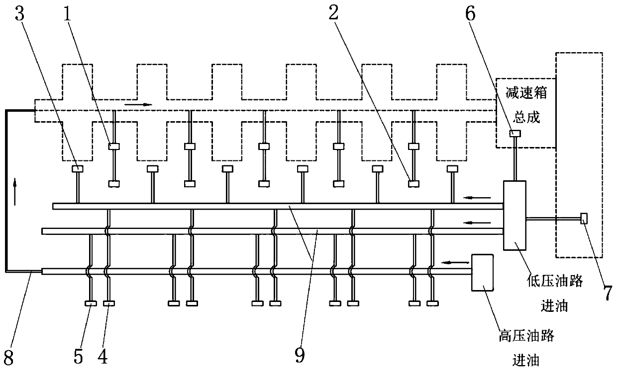
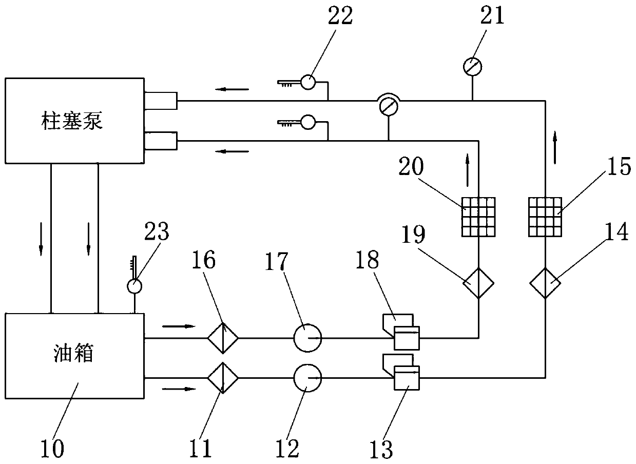
[0032] Such as Figures 1 to 2 As shown, a high-low pressure lubrication system for a high-power plunger pump includes a high-pressure oil circuit 8 and a low-pressure oil circuit 9. The high-pressure oil circuit 8 is the connecting rod bearing bush 1 and the crosshead bearing bush 2 in the plunger pump. Lubrication, the low-pressure oil circuit 9 is lubricated for the crankshaft bearing 3, the crosshead slide rail, the reduction box bearing 7, and the reduction box gear pair 6 in the plunger pump. The crosshead slide rail includes a crosshead upper slide rail 4 and a crosshead lower slide rail 5 . Instead of the traditional lubricating "one-way oil supply" method, it is divided into high-pressure oil circuit 8 and low-pressure oil circuit 9 to enter the oil. The oil passage 9 mainly lubricates the crankshaft bearing 3, the crosshead slide rail, the reduction box bearing 7, and the reduction box gear pair 6, which have slightly lower lubrication requirements in comparison; oi...


PUM


Abstract

The invention discloses a high-low pressure lubricating system for a high power plunger pump. The system comprises a high pressure oilway and a low pressure oilway. The high pressure oilway lubricatesa connecting bearing bush and a crosshead bearing bush in the plunger pump, and the low pressure oilway lubricates a crankshaft bearing, a crosshead slide rail, a reduction box bearing and a reduction box gear pair in the plunger pump. The system has the beneficial effects that oil-taking is carried out by the high pressure oilway and the low pressure oilway, and the high pressure oilway lubricates the connecting bearing bush and the crosshead bearing bush in the plunger pump, and the low pressure oilway lubricates the crankshaft bearing, the crosshead slide rail, the reduction box bearing and the reduction box gear pair in the plunger pump; by supplying oil by two oil pumps, the oil supply mount of each oilway can be better guaranteed, lubricating oil is distributed better, the problem that the lubricating oil amount of each lubricating point is insufficient as the lubricating oil is not distributed uniformly due to too many lubricating branches is avoided, the utilization ratio of the lubricating oil is improved and abnormalities are reduced; the high pressure oilway and the lower pressure oilway adopt two-stage filtration, so that impurities in the lubricating oil can be reduced and the service lives of parts of the plunger pump are prolonged.

Description

technical field [0001] The invention relates to the technical field of lubrication of plunger pumps, in particular to a high-low pressure lubrication system for high-power plunger pumps. Background technique [0002] With the further development of unconventional oil and gas and shale oil and gas, the operating conditions of fracturing operations are becoming more and more complex, and the requirements for fracturing equipment, especially plunger pumps, are also getting higher and higher. In particular, unconventional oil and gas operations—shale gas fracturing operations require plunger pumps with high power, high pressure, and long-term continuous operation, which poses challenges to the service life of each moving mechanism of the plunger pump. As one of the important components of the plunger pump, the lubrication system can not only lubricate the surface of the moving parts, reduce frictional resistance and wear, but also cool the parts, take away the heat generated by ...

Claims


Application Information

Patent Timeline
IPC IPC(8): F04B53/18
CPCF04B53/18
Inventor 崔海萍崔文平王继鑫魏小淞李朋邓文杰
Owner 美国杰瑞国际有限公司
Learn More