Efficient and energy-saving air source heat pump

An air-source heat pump, energy-saving technology, used in heat pumps, lighting and heating equipment, damage protection, etc., can solve the problem of affecting the working efficiency of heat pump units, high-load intermittent heating of the four-way valve reversing system, and reducing the plate-fin combination. Heat exchange problems such as heat exchangers to achieve the effect of improving the coverage of the frosting layer, avoiding the risk of overheating, and avoiding the risk of high pressure

Inactive Publication Date: 2020-05-22
SHANGHAI INST OF TECH
View PDF6 Cites 1 Cited by
  • Summary
  • Abstract
  • Description
  • Claims
  • Application Information

AI Technical Summary

Problems solved by technology

[0003] When the existing air source heat pump system continuously supplies heat in winter, when it is in the defrosting mode, the four-way valve reversing system has the problem of intermittent heat supply and high load. The specific reason is that the plate-fin combined heat exchanger in winter When the temperature is below zero and the high-load heating mode is running, the fins of the plate-fin combined heat exchanger are likely to be covered by a frost layer, which reduces the heat transfer capacity of the plate-fin combined heat exchanger and seriously affects the working efficiency of the heat pump unit.

Method used

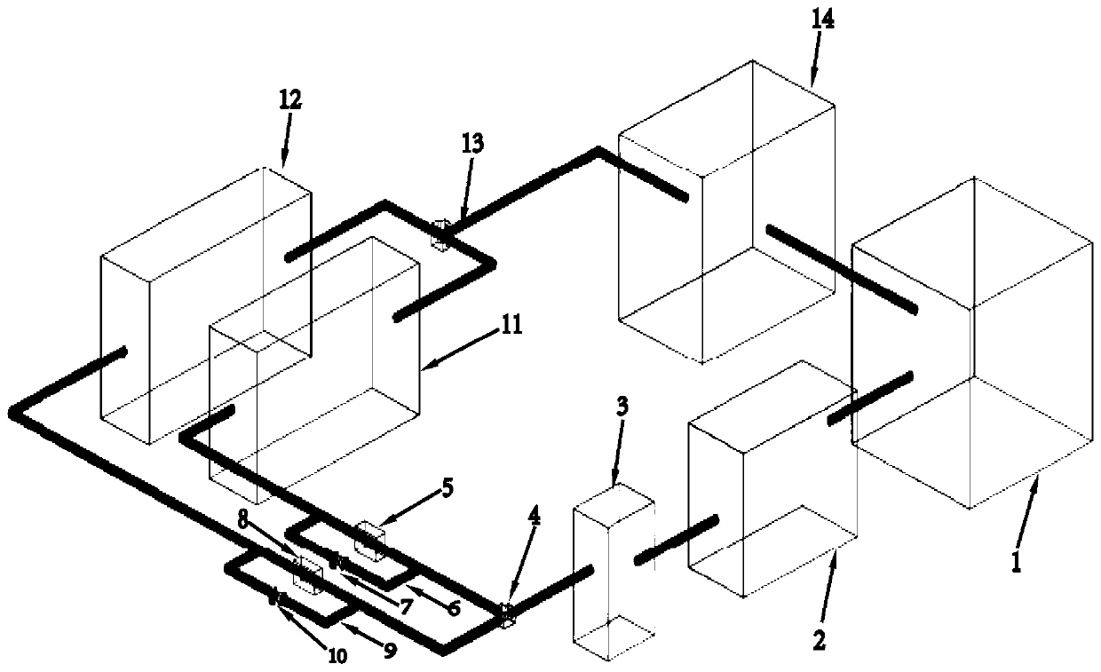
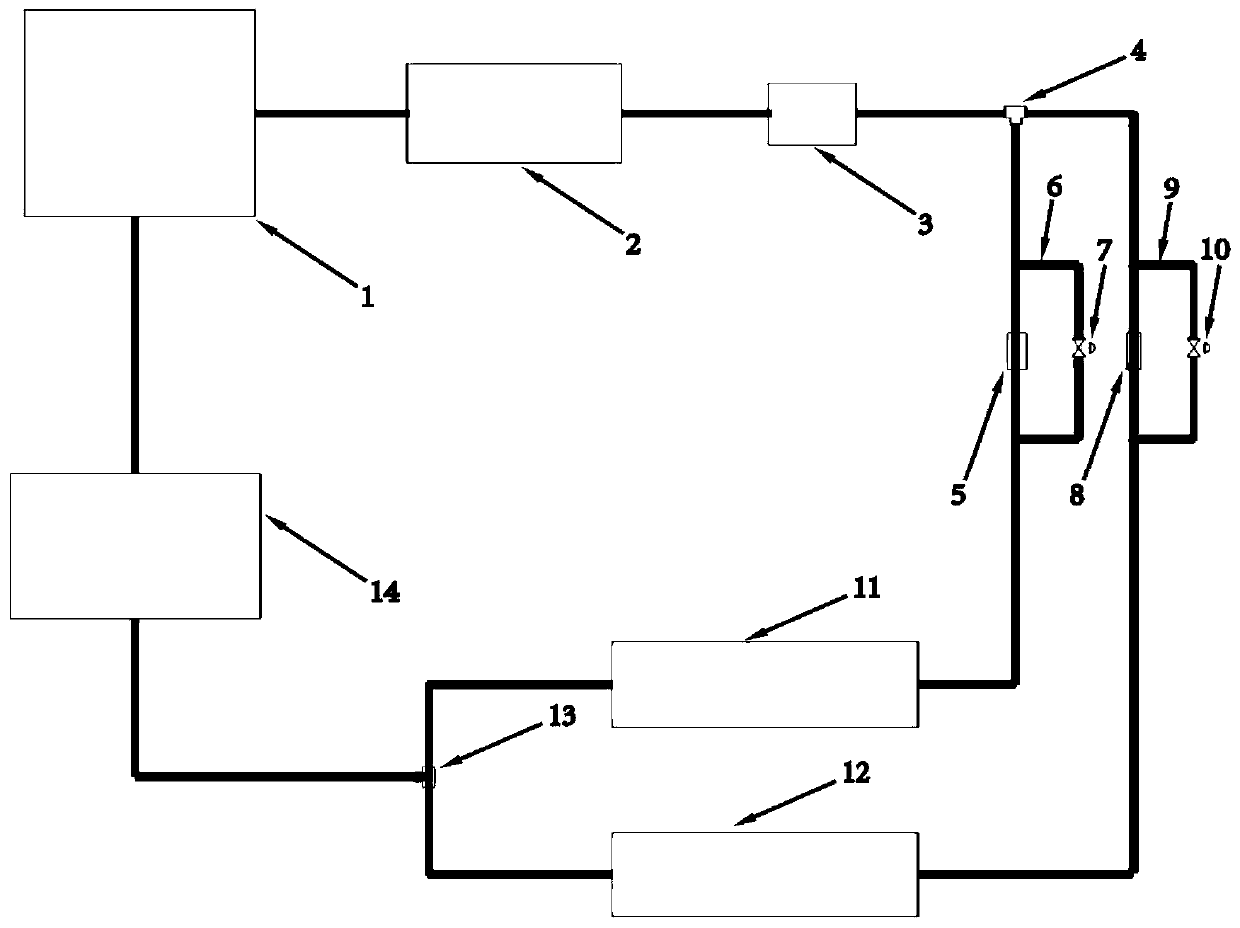
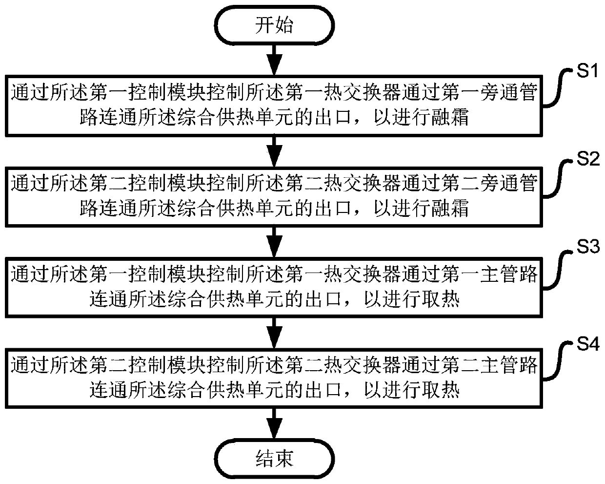

Image

  • Efficient and energy-saving air source heat pump
  • Efficient and energy-saving air source heat pump
  • Efficient and energy-saving air source heat pump

Examples


Embodiment Construction

[0035] The present invention will be described in detail below in conjunction with specific embodiments. The following examples will help those skilled in the art to further understand the present invention, but do not limit the present invention in any form. It should be noted that those skilled in the art can make several modifications and improvements without departing from the concept of the present invention. These all belong to the protection scope of the present invention.

[0036] It should be noted that when an element is referred to as being “fixed” or “disposed on” another element, it may be directly on the other element or be indirectly on the other element. When an element is referred to as being "connected to" another element, it can be directly connected to the other element or indirectly connected to the other element. In addition, the connection can be used for both fixing and circuit communication.

[0037] It is to be understood that the terms "length", "...


PUM


Abstract

The invention provides an efficient and energy-saving air source heat pump. The efficient and energy-saving air source heat pump comprises a refrigerant compression device, an integrated heat supply unit and an energy-saving module, wherein the outlet of the refrigerant compression device communicates with the inlet of the integrated heat supply unit; the energy-saving module comprises a first energy-saving module and a second energy-saving module arranged in parallel; the first energy-saving module comprises a first heat exchanger and a first control module which are arranged in series; the outlet of the first heat exchanger communicates with the inlet of the refrigerant compression device; the inlet of the first heat exchanger communicates with the outlet of the integrated heat supply unit through the first control module; the second energy-saving module comprises a second heat exchanger and a second control module which are arranged in series; the outlet of the second heat exchangercommunicates with the inlet of the refrigerant compression device; the inlet of the second heat exchanger communicates with the outlet of the integrated heat supply unit through the second control module; and the first control module and the second control module are configured to control the first heat exchanger and the second heat exchanger to alternatively perform defrosting. The efficient andenergy-saving air source heat pump can avoid the stop of system heating and the high-pressure risk of the refrigerant compression device.

Description

technical field [0001] The invention relates to the field of air source heat pumps, in particular to a high-efficiency and energy-saving air source heat pump. Background technique [0002] The air source heat pump is an energy-saving device that uses high-level energy to make heat flow from low-level heat source air to high-level heat source. It is a form of heat pump. As the name implies, a heat pump is like a pump, which can convert low-level thermal energy that cannot be directly used (such as the heat contained in air, soil, and water) into high-level thermal energy that can be used, thereby saving some high-level energy (such as coal, gas, oil, etc.) , electricity, etc.) purpose. [0003] When the existing air source heat pump system continuously supplies heat in winter, when it is in the defrosting mode, the four-way valve reversing system has the problem of intermittent heat supply and high load. The specific reason is that the plate-fin combined heat exchanger in w...

Claims


Application Information

Patent Timeline
Patent Type & Authority Applications(China)
IPC IPC(8): F25B30/06F25B47/00F25B49/02F25B41/04F25B41/06F25B41/20F25B41/325
CPCF25B30/06F25B47/00F25B49/02F25B2600/2513F25B2600/25F25B41/31F25B41/20
Inventor 谷伟彭章娥白鹤鹤
Owner SHANGHAI INST OF TECH
Why Eureka
Try Eureka