High-vibration-resistance gas density relay

A technology of gas density and relay, applied in high-voltage/high-current switches, instruments, circuits, etc., can solve problems such as poor sealing effect, aging of sealing rings, and loss of users, and achieve good sealing technology, good anti-vibration performance, and good appearance small effect

Pending Publication Date: 2020-05-22
SHANGHAI ROYE ELECTRICAL CO LTD
View PDF10 Cites 2 Cited by
  • Summary
  • Abstract
  • Description
  • Claims
  • Application Information

AI Technical Summary

Problems solved by technology

However, the sealing between the observation window (table glass) and the housing is to be sealed on the arc surface (or small arc surface). loss, even security issues, so there is an urgent need for innovation

Method used


Image

  • High-vibration-resistance gas density relay
  • High-vibration-resistance gas density relay
  • High-vibration-resistance gas density relay

Examples


Embodiment 1

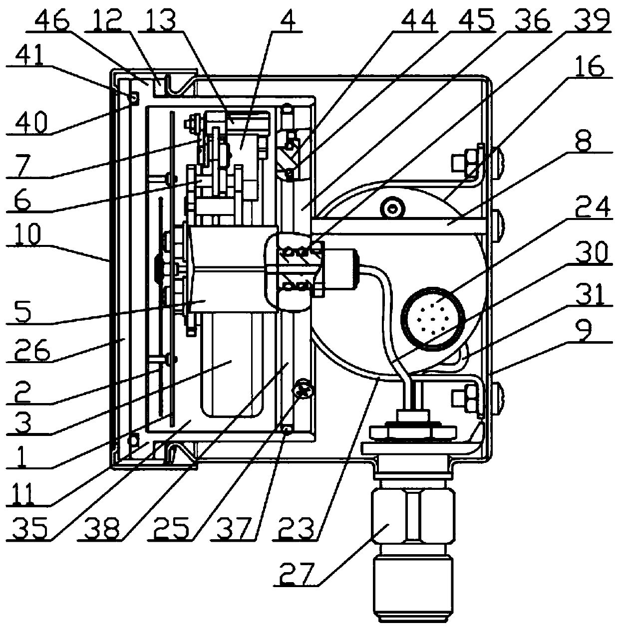
[0052] The high anti-vibration gas density relay in this embodiment, such as Figure 1-5 As shown, it includes a relay casing 9, a signal control mechanism and an indication display mechanism. A sealed cabin 35 is arranged in the relay casing 9, and the indication display mechanism is arranged in the sealed cabin 35. The sealed cabin 35 is filled with anti-vibration oil or sealed with Gas; the signal control mechanism is arranged in the relay housing 9 and outside the sealed cabin 35; the signal control mechanism and the indication display mechanism communicate with each other on the gas circuit;

[0053] The signal control mechanism includes a bellows 17, a second sealed cavity 21, a first sealed cavity 22, a signal generator 19 and a signal adjustment mechanism 20, and the bellows 17 is arranged in the second sealed cavity 21; one end of the bellows 17 is sealed , the other end of the bellows 17 communicates with electrical equipment, and a compensation gas is arranged in th...

Embodiment 2

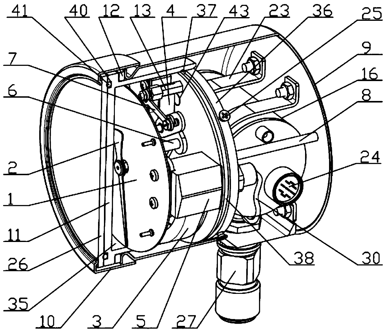
[0078] The difference between this embodiment and Embodiment 1 is that: Figure 6-7As shown, the table cover 10 is a high table cover 10, that is, the height of the table cover 10 in this embodiment is much higher than that of the table cover 10 in the first embodiment, at least 20mm higher; Outside the front glass 26 and the watch glass 11 , the height of the side wall of the watch cover 10 is higher than the height of the side wall of the watch glass 11 , and a gasket is arranged between the top open end of the relay housing 9 and the display chassis 36 . In this embodiment, the fixing piece 23 is made of angle steel, the control housing 16 of the signal control mechanism is welded together with the fixing piece 23, and then the fixing piece 23 is fixed on the bottom of the housing by several screws.

Embodiment 3

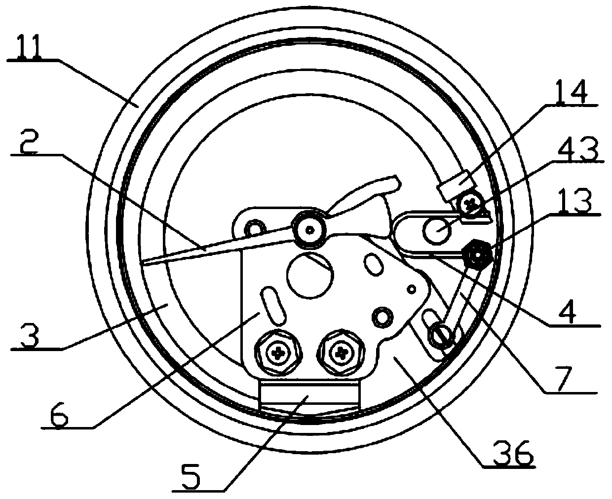
[0080] The difference between this embodiment and Embodiment 1 is that: Figure 8 As shown, the signal control mechanism also includes a control housing 16, a first sealing member 15, a second sealing member 18, a third sealing member 32, a plugging bellows 34 and an outlet connection seat 24; the outlet connection seat 24 (not shown in the figure) (out) sealed and fixed on the control housing 16, the third sealing member 32 is arranged in the control housing 16, the third sealing member 32 divides the inside of the control housing 16 into the second sealed cavity 21 and the signal adjustment cavity, and the bellows 17 is arranged in In the second sealing cavity 21, one end of the bellows 17 is welded on the first sealing member 15, and the other end is welded on the second sealing member 18. The first sealing cavity 22 is inside the bellows 17, and the first sealing cavity 22 is filled with compensation gas to form a sealed compensation gas chamber; one end of the plugging be...


PUM


Abstract

The invention discloses a high-vibration-resistance gas density relay. The high-vibration-resistance gas density relay comprises a shell, a signal control mechanism arranged in the shell and an indicating value display mechanism independent of the signal control mechanism. The signal control mechanism mainly comprises at least one corrugated pipe, a sealed compensation air chamber, a signal generator and a signal adjusting mechanism. The corrugated pipe is perpendicular to the side wall of the shell. A relatively independent sealed cabin for mounting the indicating value display mechanism is arranged in the shell; and the sealed cabin is filled with anti-vibration oil, or gas is sealed in the sealed cavity. The indicating value display part mainly comprises a Bourdon tube, a base, an end seat, a movement, pointers and a dial. The high-vibration-resistance gas density relay has the advantages of being free of oil leakage, good in vibration resistance, high in precision, good in electrical performance, thin in appearance and long in service life.

Description

technical field [0001] The invention relates to the technical field of power equipment, in particular to a high-vibration-resistant gas density relay. Background technique [0002] At present, oil-free gas density relays with micro switches as the contacts are generally used to monitor the gas density in electrical equipment. Although the micro switches used in this gas density relay have the advantages of good electrical performance, but due to the All have operating arms, and their displacement is limited, so the accuracy is poor. What is more prominent is that the length of the contact operating arm in its structure is longer, and it is a cantilever beam. When the switch is operated, the contact operating arm vibrates greatly, which in turn causes the gas density relay to malfunction or even damage the micro. Flip the switch and completely lose performance. In short, the anti-vibration performance is poor, the precision performance is poor, and the range display range i...

Claims


Application Information

Patent Timeline
Patent Type & Authority Applications(China)
IPC IPC(8): H01H35/32H01H35/26
CPCH01H35/32H01H35/26H01H33/563G01N9/266H01H35/2657H01H35/2671
Inventor 罗立波张雪珺常敏贺兵申晓礼金海勇
Owner SHANGHAI ROYE ELECTRICAL CO LTD
Why Eureka
Try Eureka