Antenna with special-shaped radiator and equipment

A radiator and antenna technology, applied in the field of communication, can solve the problems of affecting the isolation of radio frequency signals, increasing the difficulty of wiring between radio frequency signals and other signals, and reducing the complete space

Inactive Publication Date: 2020-05-22
HANGZHOU TUYA INFORMATION TECH CO LTD
View PDF7 Cites 1 Cited by
  • Summary
  • Abstract
  • Description
  • Claims
  • Application Information

AI Technical Summary

Problems solved by technology

These devices have higher and higher requirements for their own volume, requiring the volume to be as small as possible, which also makes the antenna design in the device more and more difficult
The antenna is set on the clear area of ​​the substrate, and usually includes a radiator, a feed point conductor, a feed point, and a ground point. When the antenna in the prior art sets the feed point and the ground point, the feed point and the ground point are usually set near the substrate. In this case, if the RF module and the RF traces are also placed at the center of the substrate, although this method can ensure the isolation of the RF and the length of the RF traces is relatively short, it leaves space for the substrate on the substrate. The complete space of other devices is significantly reduced, which is not convenient for the layout of other devices on the substrate; if the RF module and RF traces are placed close to the frame, this method can leave more complete space for other devices on the substrate , but it will make the RF trace a "U" shape or " "shaped loop, which causes the distance between the input and output ends of the RF trace to be relatively close, which increases the coupling between signals and affects the isolation of the RF signal; and the length of the required RF trace is longer, which increases the RF trace. The insertion loss of the line (including skin loss and dielectric loss) also increases the difficulty of routing between radio frequency signals and other signals

Method used


Image

  • Antenna with special-shaped radiator and equipment
  • Antenna with special-shaped radiator and equipment
  • Antenna with special-shaped radiator and equipment

Examples


Embodiment Construction

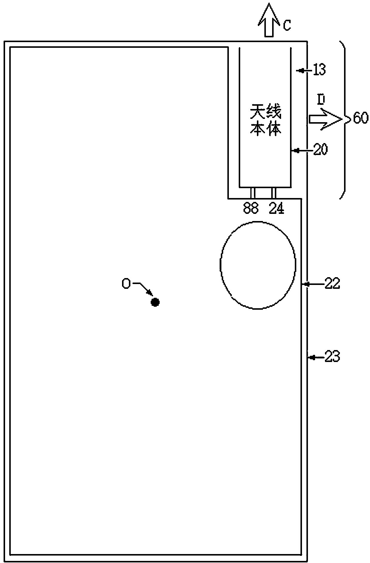
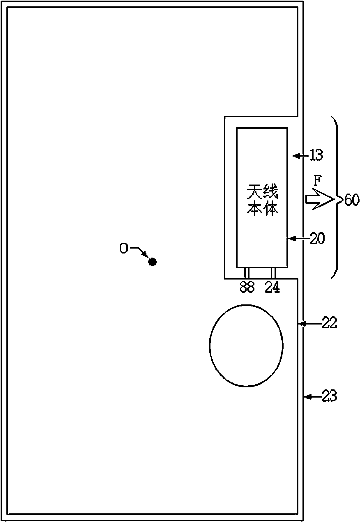
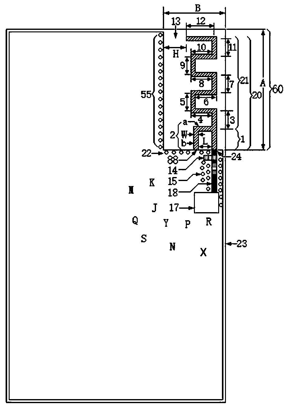
[0038] The core of the present invention is to provide a device and an antenna with special-shaped radiators, which can leave more complete space for other devices on the substrate, facilitate the layout of other devices, and the radio frequency wiring will not be in a "U" shape or a "U" shape. ” shape, the length of the required RF trace is shorter, reducing the line loss.

[0039] In order to make the purpose, technical solutions and advantages of the embodiments of the present invention clearer, the technical solutions in the embodiments of the present invention will be clearly and completely described below in conjunction with the drawings in the embodiments of the present invention. Obviously, the described embodiments It is a part of embodiments of the present invention, but not all embodiments. Based on the embodiments of the present invention, all other embodiments obtained by persons of ordinary skill in the art without making creative efforts belong to the protectio...


PUM


Abstract

The invention discloses an antenna with a special-shaped radiator. A long-strip-shaped clearance area is arranged on the base plate. The strip-shaped clearance area is arranged at the frame of the substrate. According to the invention, the grounding point and the feed point are arranged at one end, close to the center of the substrate, of the long-strip-shaped clearance area in the length direction; and because the length of the short end is short, based on the setting mode, the radio frequency module can be arranged close to the substrate frame connected with the short end, more complete space is reserved for other devices on the substrate, the layout of the other devices is facilitated, the radio frequency wiring is not U-shaped or U-shaped, the required radio frequency wiring is shorter, the probability of being interfered by other signal wiring or power supply wiring is reduced, and meanwhile, the insertion loss of the radio frequency wiring is also reduced. The invention further discloses equipment which has the same effect as the antenna.

Description

technical field [0001] The invention relates to the technical field of communication, in particular to an antenna and equipment with a special-shaped radiator. Background technique [0002] With the development of 5G communication technology, more and more devices such as Internet of Things devices, smart wearable devices, and security monitoring devices are being used. These devices have higher and higher requirements on their own volume, and require the volume to be as small as possible, which also makes the antenna design in the device more and more difficult. The antenna is set on the clear area of ​​the substrate, and usually includes a radiator, a feed point conductor, a feed point, and a ground point. When the antenna in the prior art sets the feed point and the ground point, the feed point and the ground point are usually set near the substrate. In this case, if the RF module and the RF traces are also placed at the center of the substrate, although this method can ...

Claims


Application Information

Patent Timeline
Patent Type & Authority Applications(China)
IPC IPC(8): H01Q1/36H01Q1/38H01Q1/50
CPCH01Q1/36H01Q1/38H01Q1/50
Inventor 廖建兴
Owner HANGZHOU TUYA INFORMATION TECH CO LTD
Why Eureka
Try Eureka