Clock duty ratio calibration circuit and clock duty ratio calibration method

A technology for calibrating circuits and duty ratios, applied to electrical components, generating electric pulses, static memory, etc., can solve problems such as the inability to adjust the duty ratio of clock signals, and the inability to ensure the correctness of DRAM read data, etc.

Pending Publication Date: 2020-05-22
CHANGXIN MEMORY TECH INC
View PDF0 Cites 0 Cited by
  • Summary
  • Abstract
  • Description
  • Claims
  • Application Information

AI Technical Summary

Problems solved by technology

However, the existing clock calibration circuit cannot quickly and accurately adjust the duty cycl

Method used


Image

  • Clock duty ratio calibration circuit and clock duty ratio calibration method
  • Clock duty ratio calibration circuit and clock duty ratio calibration method
  • Clock duty ratio calibration circuit and clock duty ratio calibration method

Examples


Example Embodiment

[0056] In the following, only certain exemplary embodiments are briefly described. As those skilled in the art can realize, the described embodiments may be modified in various different ways without departing from the spirit or scope of the present invention. Therefore, the drawings and description are to be regarded as illustrative in nature and not restrictive.
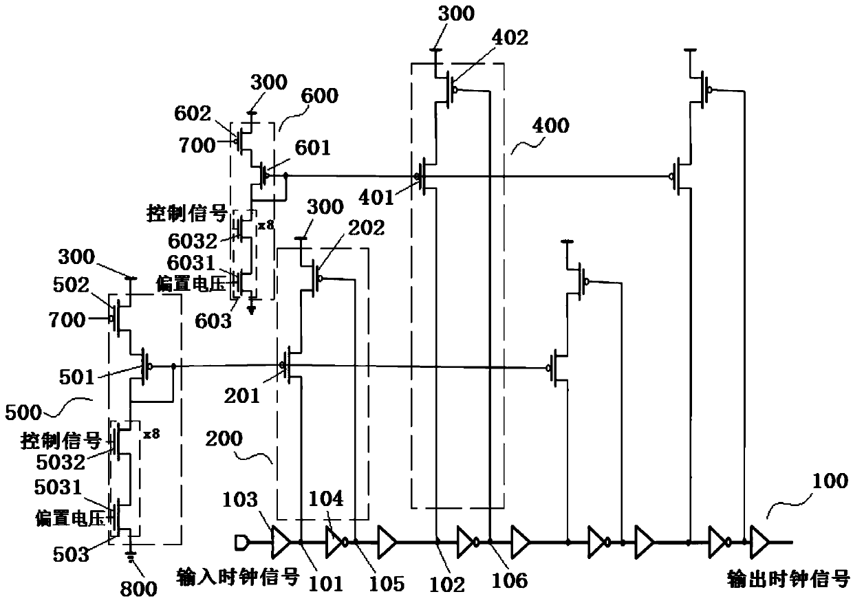
[0057] In the first aspect, an embodiment of the present invention provides a clock duty cycle calibration circuit, such as figure 1 Shown, including:

[0058] The transmission circuit 100 is configured to receive an input clock signal and send an output clock signal. The transmission circuit 100 has at least one set of a first node 101 and a second node 102.

[0059] The first pull-up circuit 200 is connected between the first node 101 and the power supply voltage 300 for charging the first node 101.

[0060] The second pull-up circuit 400 is connected between the second node 102 and the power supply voltage 300 and is u...


PUM


Abstract

The embodiment of the invention provides a clock duty ratio calibration circuit and calibration method, and the circuit comprises a transmission circuit for receiving an input clock signal and sendingan output clock signal, wherein the transmission circuit is provided with a first node and a second node; a first pull-up circuit which is connected to the first node and charges the first node; a second pull-up circuit which is connected to a second node and charges the second node; a first pull-up current adjusting circuit which is connected with the first pull-up circuit, wherein the chargingrate of the first pull-up circuit to the first node is changed by changing the pull-up current of the first node so as to adjust the duty ratio of the output clock signal; and a second pull-up currentadjusting circuit which is connected with the second pull-up circuit, wherein the charging rate of the second pull-up circuit to the second node is changed by changing the pull-up current of the second node so as to adjust the duty ratio of the output clock signal. According to the embodiment of the invention, different nodes on the transmission circuit are charged, so the duty ratio of the output clock signal of the transmission circuit can be quickly and accurately adjusted to about 50%.

Description

technical field [0001] The invention relates to the field of semiconductor integrated circuits, in particular to a clock duty ratio calibration circuit and a calibration method. Background technique [0002] This section is intended to provide a background or context to embodiments of the invention that are recited in the claims. The descriptions herein are not admitted to be prior art by inclusion in this section. [0003] In the field of DRAM (Dynamic Random Access Memory, dynamic random access memory), DDR (Double Data Rate SDRAM, double-rate synchronous dynamic random access memory) technology triggers reading data on the upper and lower edges of the clock, so a good duty cycle Clocks are also more important in the DRAM world. However, the existing clock calibration circuit cannot quickly and accurately adjust the duty cycle of the clock signal, thus failing to ensure the correctness of the data read from the entire DRAM. Contents of the invention [0004] Embodimen...

Claims


Application Information

Patent Timeline
IPC IPC(8): H03K3/017G11C11/4076
CPCG11C11/4076H03K3/017
Inventor 不公告发明人
Owner CHANGXIN MEMORY TECH INC
Why Eureka
Try Eureka