Rapid cap cutting device and method for semiconductor laser tube cap

A laser and semiconductor technology, applied in positioning devices, clamping, supports, etc., can solve problems such as difficult control of strength, failure of lasers, laborious cutting, etc., to achieve the effect of improving cutting efficiency, increasing contact area, and improving product quality

Active Publication Date: 2020-05-26
潍坊华光光电子有限公司
View PDF8 Cites 3 Cited by
  • Summary
  • Abstract
  • Description
  • Claims
  • Application Information

AI Technical Summary

Problems solved by technology

Using this method to cut the cap is inefficient, only one cap can be cut at a time, and the cap is made of aluminum, it is laborious to cut, and it is difficult to control the force during the cutting process, which is very easy to cause deformation of the cap, thus touching The chip or gold wire structure inside the laser causes the laser to fail. During the clamping process, the three tube legs are subjected to external forces, which may easily cause the tube legs to close together due to deformation, affecting the use effect

Method used


Image

  • Rapid cap cutting device and method for semiconductor laser tube cap
  • Rapid cap cutting device and method for semiconductor laser tube cap
  • Rapid cap cutting device and method for semiconductor laser tube cap

Examples


Embodiment 1

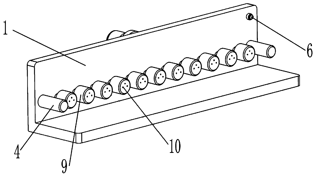
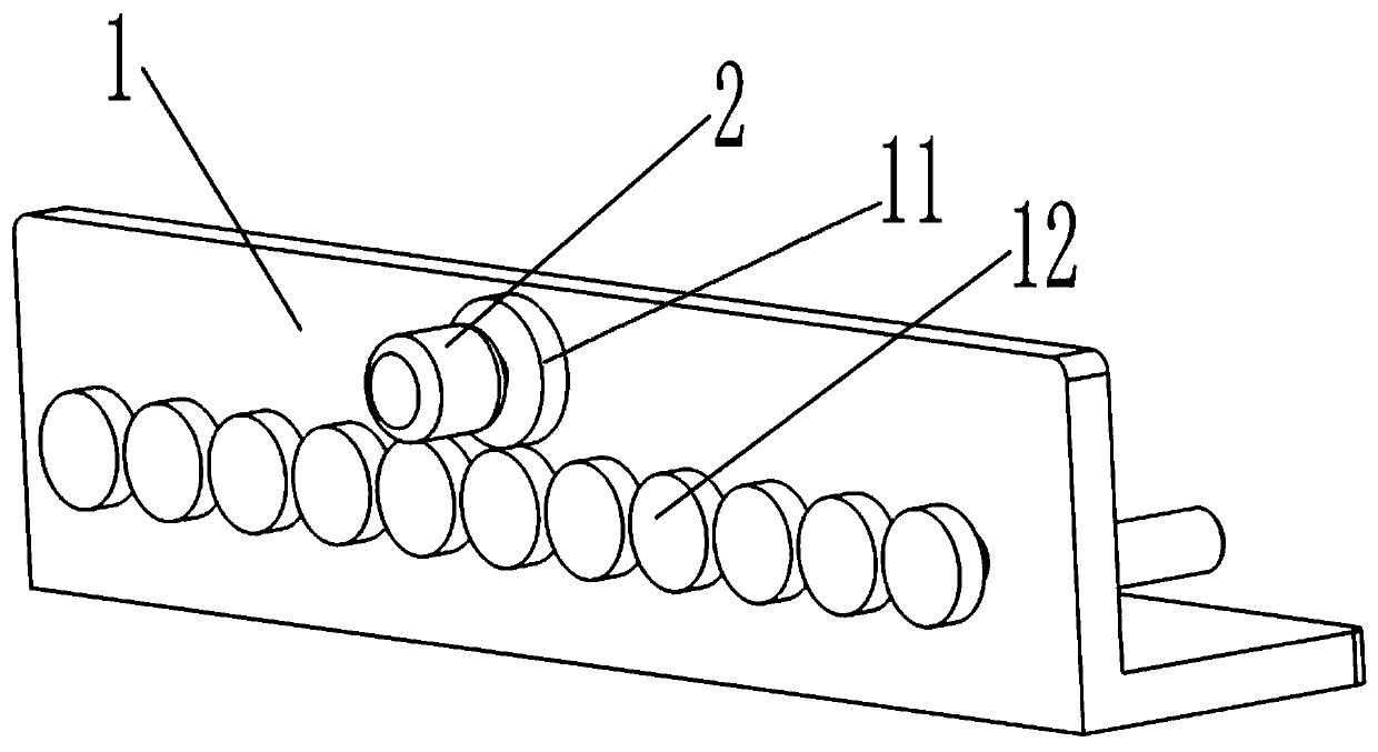
[0042] The drive mechanism of the fixed seat can be the following structure, which includes the motor 2 installed on the base 1, the gear I 11 installed on the output shaft of the motor 2, and the gear II 12 installed on the fixed seat 9, and every two adjacent gears The IIs 12 mesh with each other, and the gear I 11 and a gear II 12 mesh with each other. When the motor 2 rotates, it drives the gear I 11 to rotate, and when the gear I 11 rotates, it drives the gear II 12 meshed with it to rotate. Since each gear II 12 is meshed with each other, the purpose of the motor 2 driving each gear II 12 to rotate synchronously is realized. The rotation of the laser 26 is achieved.

Embodiment 2

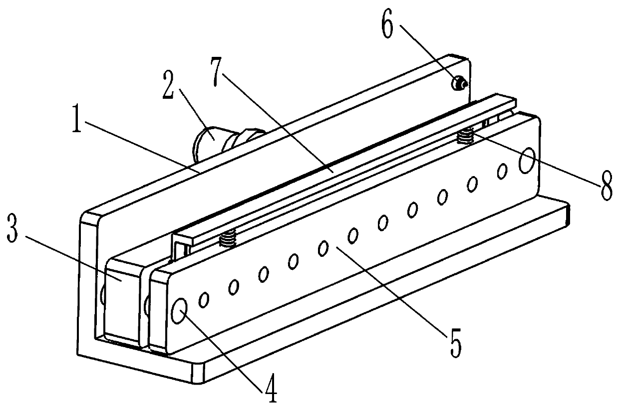
[0044] It also includes a tube cap fixing plate 5, which is arranged at the front end of the laser fixing plate 3, and guide holes II 18 matching with the guide rod 4 are respectively provided at the left and right ends of the tube cap, and the laser fixing plate 3 is inserted into the guide rod 4 through the guide hole II 18 On the cap fixing plate 5, N circular holes II 19 matching the caps 29 are provided at intervals along the horizontal direction, and the head ends of the caps 29 are inserted into the corresponding circular holes II 19. Pass the tube cap fixing plate 5 through the guide hole II 18 and insert it on the guide rod 4, then push it toward the direction of the laser fixing plate 3 so that each tube cap 29 is inserted into the round hole II 19 . Since the tube cap 29 is supported and fixed by the round hole II 19, the tube cap 29 is more stable and firm when the cutting knife 7 presses down to cut the tube cap 29, avoiding the one-sided support of the laser 26 by...

Embodiment 3

[0046] It also includes a switch 6 installed on the base 1, and the motor 2 is connected to the power supply through the switch 6. The opening and closing of the motor 2 can be conveniently controlled by the switch 6, and the control of the rotation or stop of the fixed seat 9 can be realized conveniently, thereby improving the convenience of operation.


PUM


Abstract

A rapid cap cutting device for a semiconductor laser tube cap comprises a base, N fixing seats, a fixing seat driving mechanism, a laser fixing plate and a cutting knife. The laser fixing plate can beinstalled in place after being inserted on a guide rod through a guide hole I, tube legs of lasers are inserted into corresponding insertion holes in the fixing seats, the fixing seat driving mechanism drives each fixing seat to rotate, rotation of each laser is achieved, the cutting knife is pressed downwards, a cutting edge below the cutting knife is in contact with the corresponding tube cap,and the rotating tube cap is cut off by the cutting edge. The tube legs are inserted into the insertion holes, so that the tube legs can be effectively protected, and the tube legs cannot be bent andfolded. When the tube cap is cut, the cutting force on the tube cap is uniform, the end face of the cut tube cap is tidy, deformation of the tube cap during cutting can not occur, damage to the insides of the lasers can not occur, and the product quality of cap cutting is improved.

Description

technical field [0001] The invention relates to the technical field of semiconductor lasers, in particular to a fast cap cutting device and a cap cutting method for a semiconductor laser tube cap. Background technique [0002] After decades of development, semiconductor lasers have become more and more well-known to the society and have been applied in many fields. The photoelectric conversion efficiency of semiconductor lasers is above 60%, which is much higher than that of other similar products. The advantages of low energy consumption, less heat accumulation in the device, long life, good collimation, and long lighting distance are more and more widely used as an emerging technology in similar industries in society. The various advantages of semiconductor lasers determine that they are getting more and more attention from all walks of life. [0003] Due to the advantages of small size, light weight, high efficiency, long life, easy modulation and low price, semiconducto...

Claims


Application Information

Patent Timeline
Patent Type & Authority Applications(China)
IPC IPC(8): B23D79/00B23Q3/06
CPCB23D79/00B23Q3/061B23Q3/062
Inventor 张广明汤庆敏赵克宁贾旭涛
Owner 潍坊华光光电子有限公司
Why Eureka
Try Eureka