Method for production of electric power steering systems, electric power steering system

A technology of electric power steering and steering system, which is applied in the manufacture of motor generators, electric steering mechanisms, power steering mechanisms, etc., and can solve the problems of expensive and complicated preload adjustment

Inactive Publication Date: 2020-05-26
TRW AUTOMOTIVE GMBH
View PDF0 Cites 1 Cited by
  • Summary
  • Abstract
  • Description
  • Claims
  • Application Information

AI Technical Summary

Problems solved by technology

Due to the large number of influencing parameters and components involved, the corresponding adjustment of the preload force can be very expensive and / or complex

Method used


Image

  • Method for production of electric power steering systems, electric power steering system
  • Method for production of electric power steering systems, electric power steering system
  • Method for production of electric power steering systems, electric power steering system

Examples


Embodiment Construction

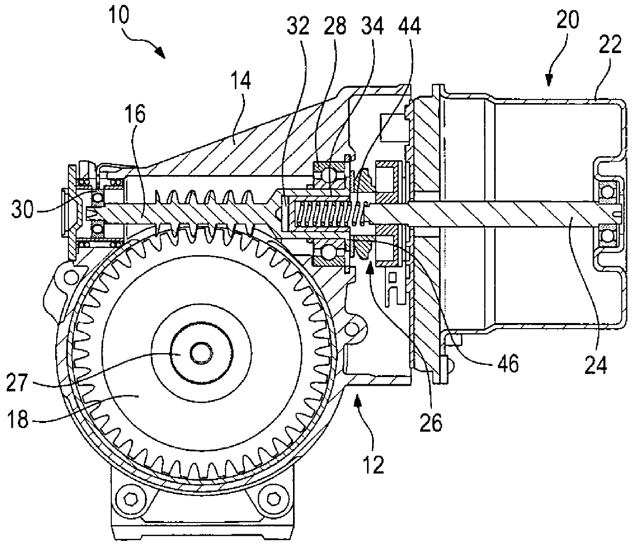
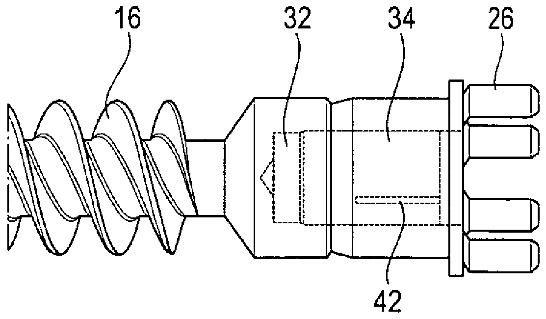
[0031] figure 1 A part of an electric power steering system 10 is schematically shown, which comprises a worm gear 12 with a housing 14 in which a worm shaft 16 and a worm wheel 18 are mounted, the worm shaft 16 and the worm wheel 18 being in meshing.

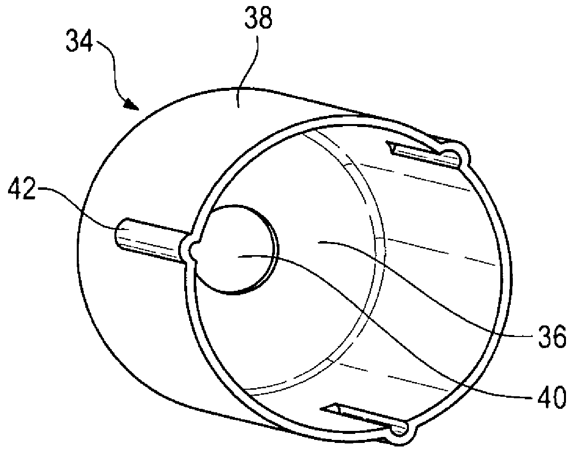
[0032] Furthermore, the steering system 10 includes an electric motor 20 with a motor housing 22 and a drive shaft 24 which is connected to the worm shaft 16 in a rotationally fixed manner via a coupling device 26 .

[0033] The electric motor 20 is an assist motor of the steering system 10 . The auxiliary force exerted by the electric motor 20 is transmitted via the drive shaft 24 to the coupling 26 , from the coupling to the worm shaft 16 , from the worm shaft to the worm wheel 18 and thus to the steering column 19 .

[0034] exist figure 1 In the illustrated embodiment, the worm gear 18 is connected in a non-rotatable manner to a steering column 27 of the steering system 10 . The steering system 10 is therefore designed ...


PUM


Abstract

The invention relates to a method to manufacture electric power steering systems (10). First, an electric motor (20) having a drive shaft (24), a coupling device (26), and a worm gear (12) having a worm shaft (16) are provided. Then, an adjusting sleeve is provided, and an individual axial position of each adjusting sleeve in its associated opening is determined in order to achieve a specific axial preloading force on the worm shaft. The adjusting sleeve (34) is press-fitted into the axial opening (32) in the determined axial position, and a spring element (44) is installed in the adjusting sleeve (34) so that the spring element is supported on one end axially on the drive shaft and on its other end it is supported axially on the adjusting sleeve (34), and said spring element acts upon theworm shaft with the preloading force in the axial direction via the adjusting sleeve. In addition, also described is an electric power steering system.

Description

technical field [0001] The invention relates to a method for producing an electric power steering system and an electric power steering system. Background technique [0002] Certain types of electric power steering systems known from the prior art comprise a worm gear through which the power assist motor of the steering system is connected to the steering column (steering system with steering column assist, usually in English Also known as "EPS column drive") or force-transmittingly connected with a pinion that meshes with the rack of the steering system (steering systems with single pinion drive or steering systems with double pinion, in English usually Also known as "pinion drive EPS" or "dual pinion EPS"). [0003] The worm shaft of the worm gear is usually rotatably mounted on the end assigned to the electric motor by means of a fixed bearing. Between the worm shaft and the drive shaft of the electric motor there is a coupling device and a pre-compression device which ...

Claims


Application Information

Patent Timeline
Patent Type & Authority Applications(China)
IPC IPC(8): B62D5/04B62D3/04
CPCB62D5/04B62D5/0445B62D3/04B62D5/0409F16H55/24H02K7/1166H02K2205/03H02K7/003H02K7/081H02K15/00F16H2057/0213F16C2326/24F16H19/02
Inventor M·约尔丹
Owner TRW AUTOMOTIVE GMBH
Why Eureka
Try Eureka