Scrap pre-heating device for a melting furnace and method for scrap pre-heating

A technology of preheating device and waste, applied in the direction of preheating fee, waste heat treatment, furnace, etc., can solve the problem of reducing the efficiency of waste preheating device and so on

Active Publication Date: 2020-05-26
INTECO MELTING & CASTING TECH GMBH
View PDF15 Cites 0 Cited by
  • Summary
  • Abstract
  • Description
  • Claims
  • Application Information

AI Technical Summary

Problems solved by technology

Thus, leaks in the equipment lead to a further reduction in the efficiency of the waste preheating device

Method used


Image

  • Scrap pre-heating device for a melting furnace and method for scrap pre-heating
  • Scrap pre-heating device for a melting furnace and method for scrap pre-heating
  • Scrap pre-heating device for a melting furnace and method for scrap pre-heating

Examples


Embodiment Construction

[0030] In the drawings, the same components and components having the same functions are denoted by the same reference numerals.

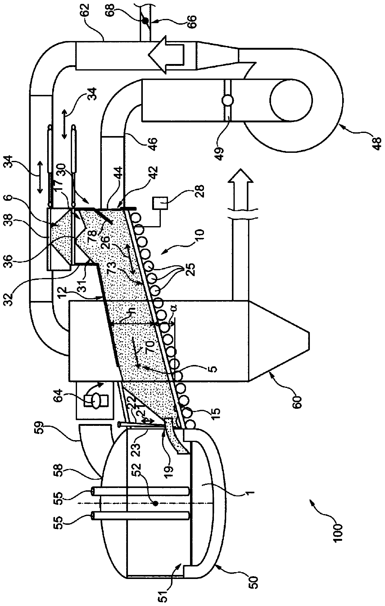
[0031] figure 1 A highly simplified example of a plant 100 for producing a melt 1 consisting of metal in a furnace 50 is shown. In a manner known per se, the furnace 50 is formed with an inner chamber 51 and can be pivoted or tilted about an axis of rotation 52 at figure 1 in the diagram perpendicular to the figure 1 The layer of the furnace 50 is extended so that the melt 1 produced in the inner chamber 51 of the furnace 50 is poured out of the furnace 50 in the region of the outlet (not shown) of the furnace 50 for subsequent processing of it. Furthermore, two of the three electrodes 55 are shown connected to a voltage source (not shown) for generating the energy required to liquefy the metal. The furnace 50 also has an upper region 58 formed in a dome-like manner and connected via a manifold 59 to a post-combustion chamber 60 .

[0032] The ...


PUM


Abstract

The invention relates to a scrap pre-heating device (10) for a melting furnace (50), having an at least substantially horizontally arranged conveyor device (15) for feeding scrap (5) between an inputregion (17) for the scrap (5) into the conveyor device (15) and a transfer region (19) for the scrap (5) from the conveyor device (15) into the melting furnace (50), wherein the conveyor device (15) is arranged at least between the input region (17) and the transfer region (19) in a scrap pre-heating housing (12) having an at least substantially closed cross-section or is covered by a scrap pre-heating housing (12) on the side facing the conveying section for the scrap (5), and having an extraction device (48) for extracting waste gases from the melting furnace (50), wherein the extraction device (48) is designed to direct the waste gases out of the transfer region (19) in the direction of the input region (17).

Description

technical field [0001] The invention relates to a waste preheating device for a furnace according to the preamble of claim 1 . Furthermore, the invention relates to a method for waste preheating of a furnace, in particular by using a waste preheating device according to the invention. Background technique [0002] Different devices are known in the prior art which use the hot exhaust gases of furnaces, in particular electric arc furnaces, to preheat the scrap for producing the melt in the furnace. Among other things, devices are known which have a shaft for conveying the waste which is arranged substantially vertically above the furnace, whereby the exhaust gas or waste heat passes through the shaft as it rises and thus ensures a good utilization of the waste heat. However, the relatively high height of such an installation consisting of a furnace and a waste preheater is disadvantageous. Another disadvantage of this type of equipment is that the scrap delivered to the fur...

Claims


Application Information

Patent Timeline
IPC IPC(8): C21C5/52C21C5/56F27B3/18F27D13/00F27D17/00
CPCC21C5/527C21C5/565F27B3/18F27D13/002F27D17/003C21C2100/06Y02P10/20
Inventor 哈拉尔德·霍尔兹格鲁伯里卡尔多·戈塔尔迪约阿希姆·埃勒米凯·马纳佐汉斯·乔格·克拉斯尼格
Owner INTECO MELTING & CASTING TECH GMBH
Why Eureka
Try Eureka