Drive control system of collaborative robot

A technology of drive control and robotics, applied in the field of robotics, can solve problems such as incompleteness, achieve high security, enrich communication interfaces, and improve the effect of robot force control

Inactive Publication Date: 2020-05-29
CHENGDU CRP ROBOT TECH CO LTD
View PDF9 Cites 4 Cited by
  • Summary
  • Abstract
  • Description
  • Claims
  • Application Information

AI Technical Summary

Problems solved by technology

[0005] Aiming at the problem of incompleteness existing in the existing collaborative robot control system, the present invention provides a collaborative robot drive control system

Method used


Image

  • Drive control system of collaborative robot

Examples


Embodiment 1

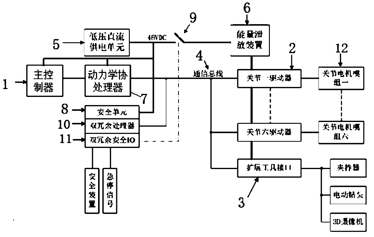
[0021] Such as figure 1 As shown, a collaborative robot drive control system includes a motion control loop, a low-voltage power supply loop and a safety control loop. The motion control loop includes a main controller 1, a dynamics coprocessor 7 and a joint motor drive controller, and the dynamics coprocessor The controller 7 is respectively connected with the main controller 1 and the joint motor drive controller, and the low-voltage power supply circuit is respectively connected with the motion control circuit and the safety control circuit.

[0022] The system integrates three loops, namely motion control loop, low-voltage power supply loop and safety control loop. The motion control loop includes a main controller 1, a dynamics coprocessor 7, and six independent robot joint drive units 2, namely joint 1 drive, joint 2 drive, joint 3 drive, joint 4 drive, joint 5 drive and joint 6 drive, Extension tool interface. The expansion tool interface 3 can be connected to auxilia...


PUM


Abstract

The invention discloses a drive control system of a collaborative robot, belongs to the technical field of robots and solves the problem of incompleteness of the existing cooperative robot control system. The drive control system comprises a motion control loop, a low-voltage power supply loop, and a safety control loop, wherein the motion control loop comprises a main controller, a dynamics coprocessor and a joint motor drive controller; the dynamics coprocessor is connected to the main controller and the joint motor drive controller; and the low-voltage power supply loop is connected to themotion control loop and the safety control loop. The drive control system is used for joint motor control, robot end tool control and robot safety control of the collaborative robot, and supports robot dynamics and locus interpolation to improve drag teaching and robot force control. The drive control system has a compact structure, rich communication interfaces, a powerful motion control processing unit and very high security, and is suitable for a collaborative robot system with human interaction.

Description

technical field [0001] The present invention relates to the technical field of robots, and more specifically relates to dynamic control and safety control of six joints of a collaborative robot arm, especially a driving control system of a collaborative robot. Background technique [0002] Traditional industrial robots generally include six-degree-of-freedom joints, and each joint corresponds to a motor; each joint is controlled in a centralized manner; it is mainly aimed at the position and speed control of the mechanical arm. The problems existing in traditional industrial robots are: because of the high-speed movement of the mechanical arm, it will constitute an unsafe factor for the operator of the attachment, so it is necessary to place the operating robotic arm in the actual fence or electronic fence; The perception is not sensitive; the volume is too large to be installed on the work surface. [0003] Collaborative robots are characterized by small size, light weight...

Claims


Application Information

Patent Timeline
Patent Type & Authority Applications(China)
IPC IPC(8): B25J9/16
CPCB25J9/1602B25J9/1664
Inventor 陈辉项勤建徐纯科朱路生李祥郭忠波申鹏林
Owner CHENGDU CRP ROBOT TECH CO LTD
Why Eureka
Try Eureka