Installing structure and installing method for wall body insulation board

A technology of installation structure and installation method, applied in thermal insulation, building components, building structures, etc., can solve problems such as hidden safety hazards, complex installation process, and hidden safety hazards of easily damaged surfaces, and achieve improved safety and high structural matching , Improve the effect of waterproof performance

Active Publication Date: 2020-05-29
湖北卓宝建筑节能科技有限公司
View PDF10 Cites 4 Cited by
  • Summary
  • Abstract
  • Description
  • Claims
  • Application Information

AI Technical Summary

Problems solved by technology

[0004] CN 102199932A discloses a composite thermal insulation board installation process. First, the four sides of the surface layer of each composite thermal insulation board are removed. After every two composite thermal insulation boards are connected, a rectangular through groove is formed between the two boards, and a rectangular through groove is formed in the middle of the rectangular through groove. Insert plastic expansion screws; use self-tapping screws to drive the anti-corrosion fixed parts into the wall through the expansion screws, and fasten the composite insulation board to the wall; finally use elastic sealant caulking to fill the rectangular groove ; This process is essentially still the above-mentioned installation method, and the expansion screw directly passes through the surface layer of the composite insulation board, which is eas

Method used


Image

  • Installing structure and installing method for wall body insulation board
  • Installing structure and installing method for wall body insulation board
  • Installing structure and installing method for wall body insulation board

Examples


Embodiment 1

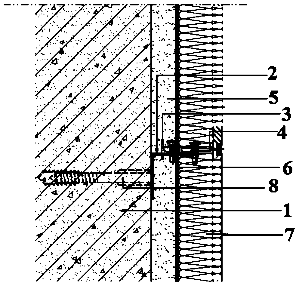
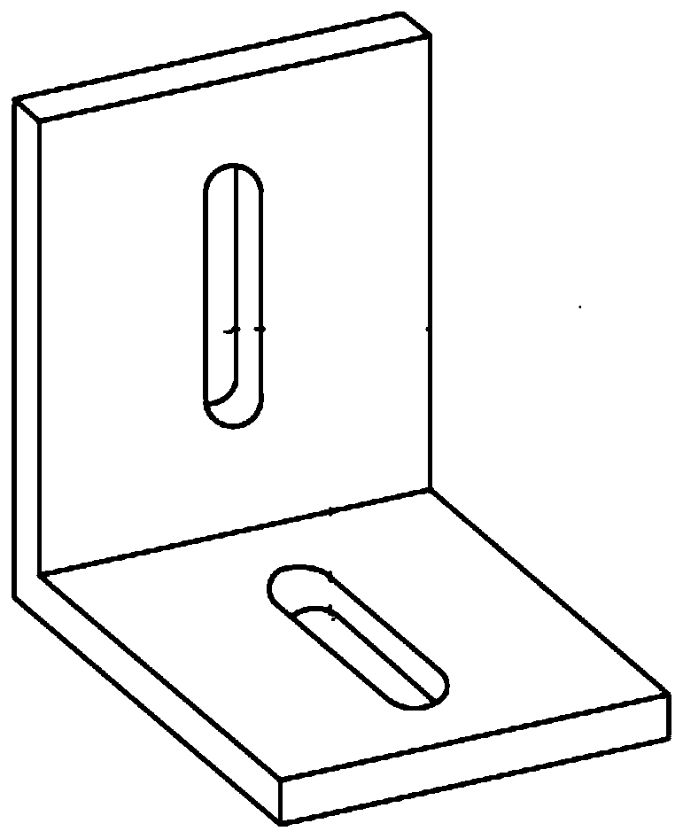
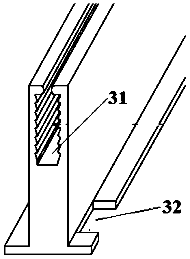
[0080] This embodiment provides an installation structure of a wall insulation board, the schematic diagram of the installation structure is as follows figure 1 As shown, it includes an L-shaped adapter 2, a T-shaped guide rail 3, a T-shaped fixture 4 and a thermal insulation board 7. The L-shaped adapter 2 includes planes and elevations perpendicular to each other, and the T-shaped guide rail 3 The main body is provided with a card slot 31, at least one of the two wings of the T-shaped guide rail 3 is provided with a groove 32, and the edge of the surface layer of the thermal insulation board 7 is grooved;

[0081] The facade of the L-shaped adapter 2 is closely attached to and fixed on the wall 1, the plane is perpendicular to the wall 1, the groove 32 on the T-shaped guide rail 3 clamps the plane of the L-shaped adapter 2, The two wings of the T-shaped guide rail 3 are parallel to the wall 1, the main body of the T-shaped guide rail 3 is fixedly connected to the plane of th...

Embodiment 2

[0089] This embodiment provides an installation structure of a wall insulation board. The installation structure includes an L-shaped adapter 2, a T-shaped guide rail 3, a T-shaped fixing member 4 and an insulation board 7. The L-shaped adapter 2 Including planes and elevations perpendicular to each other, the main part of the T-shaped guide rail 3 is provided with a slot 31, at least one of the two wings of the T-shaped guide rail 3 is provided with a groove 32, and the edge of the surface layer of the thermal insulation board 7 is grooved;

[0090] The facade of the L-shaped adapter 2 is closely attached to and fixed on the wall 1, the plane is perpendicular to the wall 1, the groove 32 on the T-shaped guide rail 3 clamps the plane of the L-shaped adapter 2, The two wings of the T-shaped guide rail 3 are parallel to the wall 1, the main body of the T-shaped guide rail 3 is fixedly connected to the plane of the L-shaped adapter 2, and the wall 1 is provided with a leveling lay...

Embodiment 3

[0097] This embodiment provides a method for installing a wall insulation board. The method can obtain the installation structure in Embodiment 1, including the following steps:

[0098] (1) First pop up the vertical control line and the horizontal control line on the wall 1, and fix the L-shaped adapter 2 to the wall 1 through the hole provided on the facade of the L-shaped adapter 2 with the expansion bolt 8 , and then the groove 32 provided on one wing of the T-shaped guide rail 3 is clamped on the plane of the L-shaped adapter 2, so that the two wings of the T-shaped guide rail 3 are parallel to the wall 1, and then the T-shaped guide rail 3 is connected with self-tapping screws. The L-shaped adapter 2 is fixedly connected, and the self-tapping screw passes through the main body of the T-shaped guide rail 3 and the hole on the plane of the L-shaped adapter 2, and then the subsequent L-shaped adapter is installed in the same way according to the sprung control line. Connect...


PUM


Abstract

The invention provides an installing structure and installing method for a wall body insulation board. The installing structure comprises an L-shaped adapter part, a T-shaped guide rail, a T-shaped fixing part and an insulation board body; the L-shaped adapter part comprises a horizontal face and a vertical face which are perpendicular to each other, a main body portion of the T-shaped guide railis provided with a clamping groove, and at least one of two wings is provided with a groove; the vertical face of the L-shaped adapter part is fixed to a wall body, and the horizontal face of the L-shaped adapter part is clamped by the groove of the T-shaped guide rail; the wall body is provided with a leveling layer, and the insulation board body is installed on the outer side of the leveling layer; and a main body of the T-shaped fixing part is inserted into the clamping groove of the T-shaped guide rail, and two wings of the T-shaped fixing part are clamped into grooves formed in the edgesof a face layer of the insulation board body. According to the installing structure for the wall body insulation board, an insulation board installing main body framework is formed through combined connection of all the assemblies, the assemblies and the insulation board both can be preformed, machining is not needed on the site, the installing technology of the insulation board is greatly simplified, and meanwhile the quality is guaranteed. Influences of the wall body structure on the installing method are small, and after the insulation board is installed, the flatness is high, and the system safety is high.

Description

technical field [0001] The invention belongs to the technical field of building structures, and relates to an installation structure and an installation method of a wall insulation board. Background technique [0002] With the development of the economy and the progress of the society, the rapid development of the construction industry and the improvement of the living environment make people have higher and higher requirements for building materials, among which the insulation of the wall is the focus of people's attention. At present, the insulation structure has gradually abandoned the practice of using a single insulation material, and the composite insulation board is the main development trend. However, in addition to the improvement of the thermal insulation effect of the thermal insulation board, its installation method is also one of the focuses of current research, which will directly affect the thermal insulation performance and safety performance. [0003] At pr...

Claims


Application Information

Patent Timeline
IPC IPC(8): E04B1/76E04B1/80
CPCE04B1/7629E04B1/80
Inventor 邹先华甘露
Owner 湖北卓宝建筑节能科技有限公司
Why Eureka
Try Eureka