Rock mass real-time wave velocity measurement and quality evaluation method

A quality evaluation and rock mass technology, applied in measuring devices, measuring propagation velocity, measuring ultrasonic/sonic/infrasonic waves, etc., can solve the problems of random intermixing and complex evolution of microstructure, and achieve low price, simple operation and strong practicability Effect

Pending Publication Date: 2020-05-29
DALIAN UNIV OF TECH
View PDF11 Cites 11 Cited by
  • Summary
  • Abstract
  • Description
  • Claims
  • Application Information

AI Technical Summary

Problems solved by technology

The internal microstructure of natural rock mass is randomly mixed, and the evolution of the cumulative damage weakening effect in the process of dynamic

Method used


Image

  • Rock mass real-time wave velocity measurement and quality evaluation method
  • Rock mass real-time wave velocity measurement and quality evaluation method
  • Rock mass real-time wave velocity measurement and quality evaluation method

Examples


Embodiment 1

[0067] The steps of a method for rock mass real-time wave velocity measurement and quality evaluation are as follows:

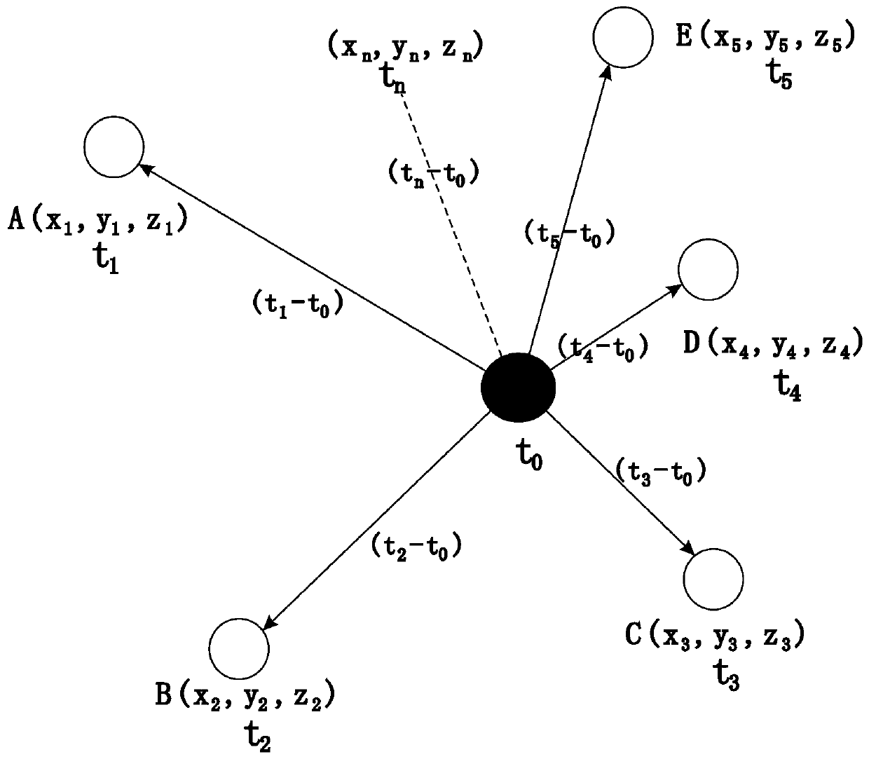
[0068] (1) First determine the coordinates of each sensor, A(x 1 ,y 1 ,z 1 ), B, (x 2 ,y 2 ,z 2 )C(x 3 ,y 3 ,z 3 ), D(x 4 ,y 4 ,z 4 ), E(x 5 ,y 5 ,z 5 )...

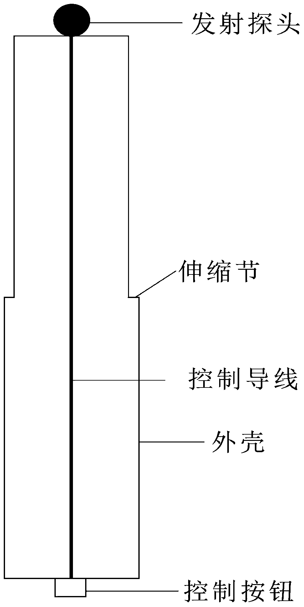
[0069] (2) Then the predetermined position 0(x 0 ,y 0 ,z 0 ) into a hole of a certain depth, and then insert the ultrasonic sending device to adjust the data processing interface of the notebook. Calculate the distance between each sensor and the ultrasonic transmission position according to the coordinates of each sensor and the coordinates of the ultrasonic transmission position, the calculation formula is as follows:

[0070]

[0071] (3) Press the button of the ultrasonic sending device to send ultrasonic waves, and at the same time when pressing, the timer of the ultrasonic sending device will count at the same time, and the initial output time is t 0 .

[0072] (4) After a pe...

Embodiment 2

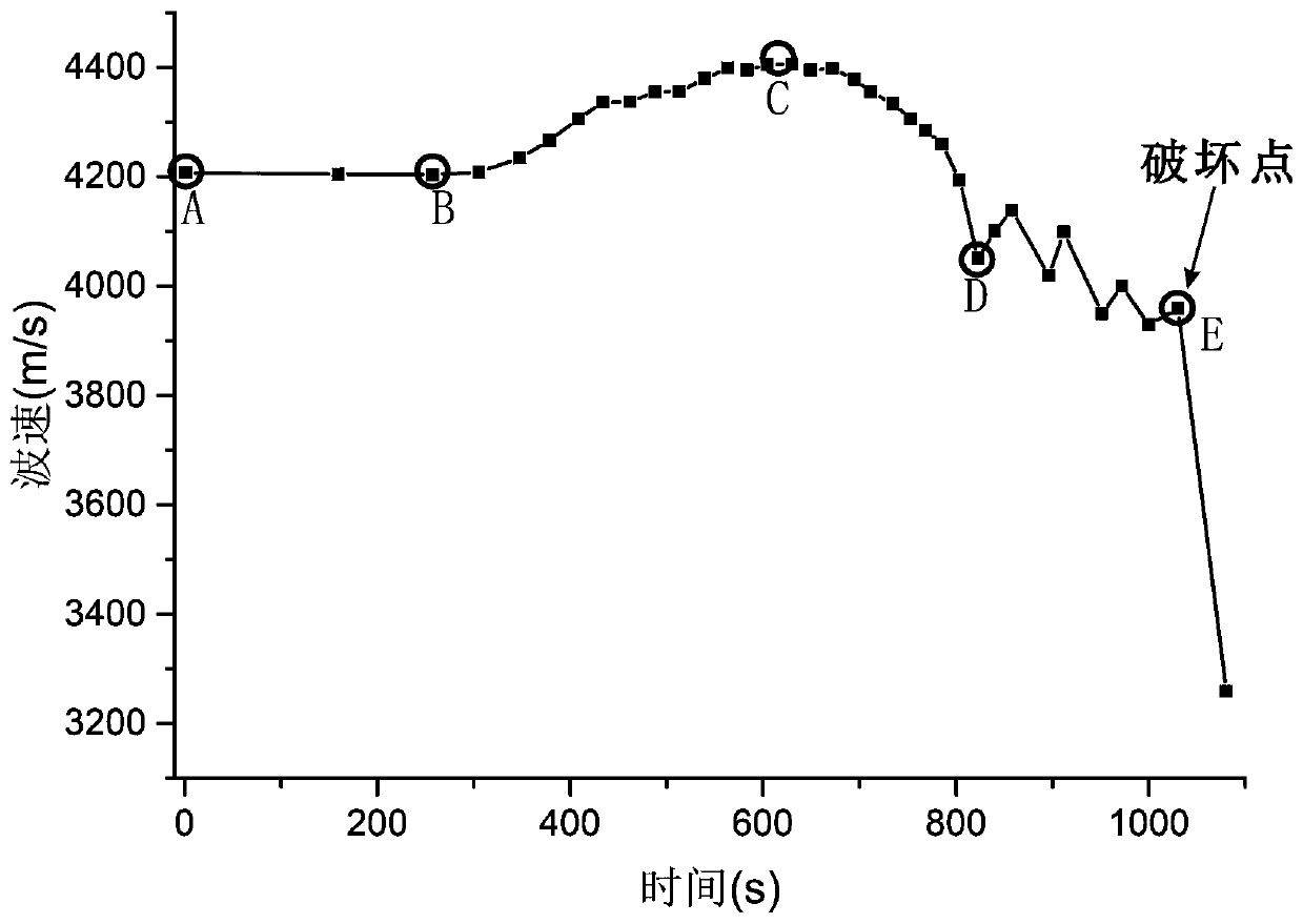
[0120] Acoustic wave is a good information carrier, and the acoustic wave velocity characteristics of rock media carry a large amount of information related to the mechanical properties and structural state of rock mass. These information can be comprehensively reflected in the changes of acoustic parameters, such as ultrasonic velocity, attenuation coefficient, waveform, frequency, frequency spectrum and amplitude, etc., through the analysis of the acoustic wave characteristics after the sound wave passes through the rock mass, it can be detected non-destructively, quickly and easily Structural properties of the interior of a rock mass. When the rock mass is affected by the excavation disturbance, the shape and size of the internal pores, cracks, and structural surfaces of the rock mass are constantly changing, and the propagation speed of the wave inside the rock mass will also change accordingly. According to the corresponding relationship, the present invention invents an ...


PUM


Abstract

The invention discloses a rock mass real-time wave velocity measurement and quality evaluation method and belongs to the technical field of rock mass engineering. The method is characterized in that abutton of an ultrasonic wave sending device is continuously pressed at different ultrasonic wave sending positions and at different time, and the speed of ultrasonic waves propagated to each sensor each time is continuously calculated, and inversion is performed according to parameter change values such as wave speed, attenuation coefficient, waveform, frequency, frequency spectrum, amplitude andthe like to obtain physical and mechanical indexes and microstructure characteristics of the rock-soil body, such as change conditions of pores and cracks, so as to analyze the stability condition ofa mine rock body. The device is advantaged in that the device is combined with a micro-seismic system, testing can be completed only by arranging an ultrasonic sending system, operation is easy, theprice is low, and practicability is high; the ultrasonic testing technology has strong advantages in the field of rock-soil testing, ultrasonic waves have geometrical acoustics and physical acousticsat the same time, directivity of the sound waves is good, and energy is high; flexibility is high, and the test time, the test frequency, the test depth and the test position can be manually controlled.

Description

technical field [0001] The invention belongs to the technical field of rock mass engineering, including mining, water conservancy and hydropower, transportation, etc., and particularly relates to a method for real-time wave velocity measurement and quality evaluation of rock mass. Background technique [0002] Rock acoustic wave testing technology has been developed based on engineering requirements since its formation. Since its development in the 1960s, it has been more and more widely used in rock mechanics engineering. The development process includes continuous improvement of testing systems and research on acoustic wave propagation in rocks Continuous solution of theoretical problems. Rock is a kind of heterogeneous anisotropic material, which contains micro-cracks and sometimes macro-defects such as cracks, cavities, and even joints. Fracture is the root of all behaviors of geological bodies, especially the expansion of rock cracks. As one of the hot issues in rock m...

Claims


Application Information

Patent Timeline
IPC IPC(8): G01N29/04G01N29/30G01H5/00
CPCG01H5/00G01N29/045G01N29/30
Inventor 唐世斌李佳明王嘉戌孙康
Owner DALIAN UNIV OF TECH
Why Eureka
Try Eureka