
A compact food processor

A technology for a food processing machine and a stand, which is applied to utensils with integral electric heating devices, kitchen utensils, household utensils, etc., can solve the problems of insufficient compact structure of food processing machines, complex structure of mixing cup components, and performance discounts such as waterproofing. , to achieve the effect of good waterproof and dustproof performance, compact and reasonable layout, and compact structure

Active Publication Date: 2022-08-09
JOYOUNG CO LTD
View PDF14 Cites 0 Cited by
  • Summary
  • Abstract
  • Description
  • Claims
  • Application Information

AI Technical Summary

Problems solved by technology

[0003] In order to better control the food processor, the prior art usually has a detection device on the top of the mixing cup assembly, and the detection device is electrically connected to the first coupler through a conductive part, so that the detection device passes through the conductive part, the first coupler, the second The coupler is electrically connected to the circuit board, and feeds back the detection signal to the circuit board in the machine base for the circuit board to control the food processor. In order to install conductive parts, an outlet is often opened on the side of the cup holder, and the outlet is directed from the outlet to The outer extension forms a receiving seat, and the conductive part enters the receiving seat from the outlet and extends upward to the detection device. Although this installation structure solves the installation problem of the conductive part, it will cause the structure of the cup holder to be more complicated, and for the sake of appearance, there is also a The handle on one side of the cup body should be extended downward to seamlessly connect with the receiving seat, but there will inevitably be gaps between the handle and the receiving seat, which will greatly reduce the waterproof performance. In addition, the structure of the cup holder is also complicated. Brings the complex structure of the entire mixing cup assembly, making the structure of the food processor not compact enough

Method used


Image

  • A compact food processor
  • A compact food processor
  • A compact food processor

Examples


Embodiment 1

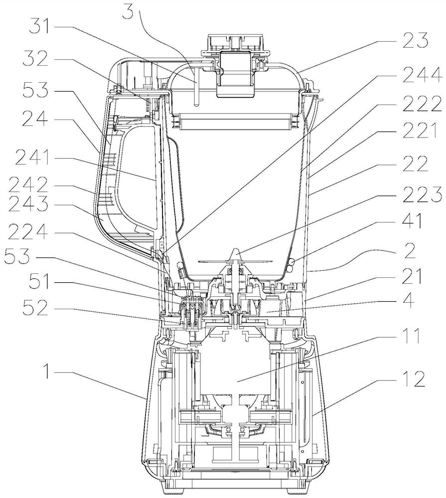
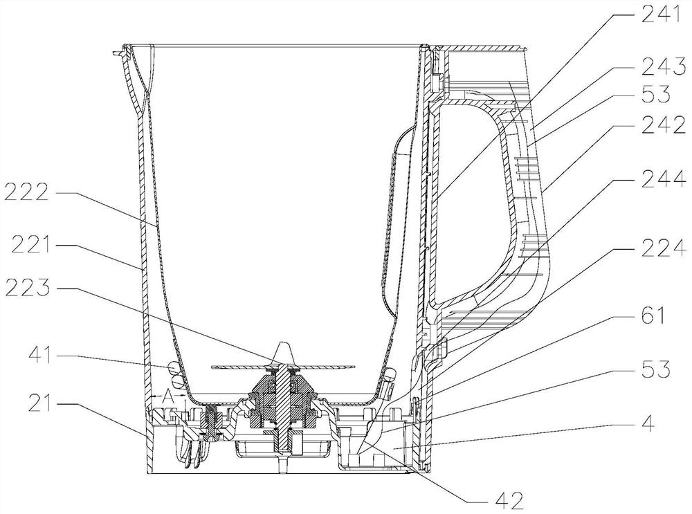
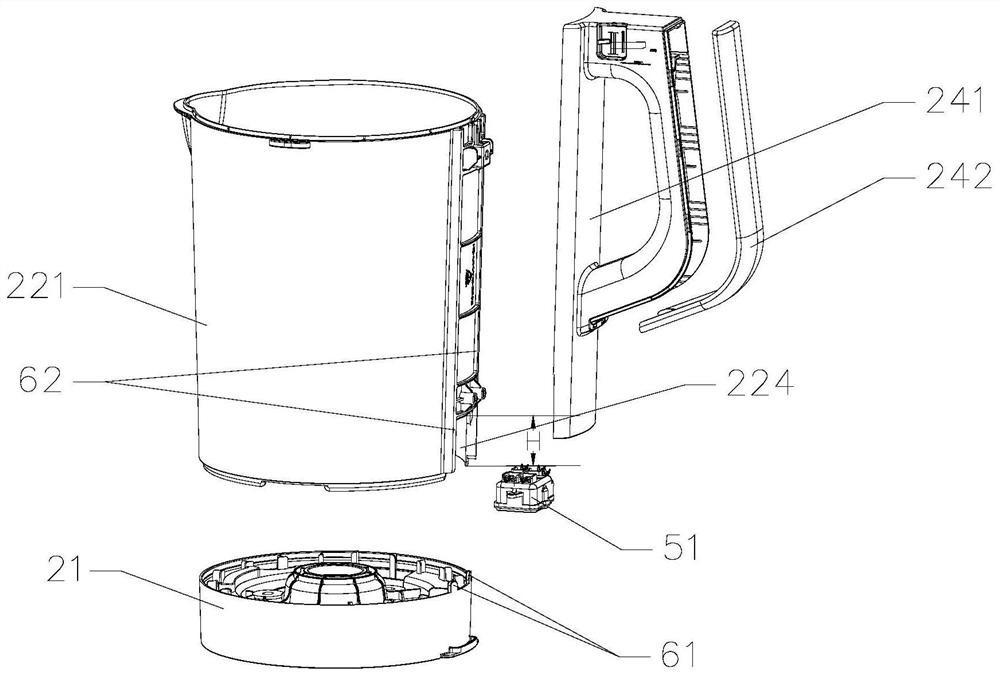
[0034] The structure of the food processor of this embodiment is as follows Figure 1 to Figure 3 As shown, the food processing machine includes a base 1, a stirring cup assembly 2 arranged on the base 1, and a detection device 3 arranged on the upper part of the stirring cup assembly 2. The base 1 is provided with a motor 11 and a circuit board 12 to stir The cup assembly 2 includes a cup base 21, a cup body 22 and a cup cover 23. The cup body 22 includes an outer cup body 221 and an inner cup body 222. The inner cup body 222 is provided with a crushing knife 223. The upper end of the motor shaft of the motor 11 runs through the machine. A lower connector is connected to the back of the base 1, and an upper connector is connected to the lower end of the cutter shaft of the crushing knife 223. When the stirring cup assembly 2 is placed in place on the base 1, the upper connector and the lower connector are matched and connected, so that the motor 11 can operate. The pulverizin...

Embodiment 2

[0053] The difference between this embodiment and the first embodiment is that the structure of the conductive member 53 is different. Figure 4 As shown, the conductive member 53 in this embodiment includes a wire 531 and a conductive sheet 532. The conductive sheet 532 is in the shape of a sheet. A clamping cavity 245 is formed between the handle body 241 and the outer cup body 221. The conductive sheet 532 is located in the clamping cavity 245. One end of the wire 531 extends into the annular cavity 4 and is electrically connected to the first coupler 51. The other end of the wire 531 extends out of the annular cavity and is connected to the conductive sheet 532. The conductive sheet 532 extends upward along the clamping cavity and is electrically connected to the detection device. The installation method is very suitable for the arrangement and installation of the rigid conductive member ie the conductive sheet 532 , and the rigid conductive member ie the conductive sheet 5...

Embodiment 3

[0056]The difference between this embodiment and Embodiment 1 and Embodiment 2 is that the structure of the detection device is different. Figure 5 As shown, the detection device 3 includes a detection switch 33 and a trigger member 34 that triggers the detection switch 33. The trigger member 34 is arranged on the cup cover 23, specifically on the mounting seat on one side of the cup cover 23, and the detection switch 33 is arranged on the handle The top of 24 is electrically connected to the conductive member 53. After the cup cover is installed in place, the mounting seat is located above the top of the handle 24. The trigger member 34 triggers the detection switch 33, and the detection switch 33 feeds back to the circuit board 12. The internal circuit of the food processor is turned on to improve the safety of the user. In this embodiment, the detection switch 33 is a micro switch, and the trigger member 34 is a contact, that is, whether the lid is closed in place can be i...


PUM


Abstract

The invention discloses a food processing machine with a compact structure, comprising a machine base, a stirring cup assembly arranged on the base, and a detection device arranged on the upper part of the stirring cup assembly. The machine base is provided with a motor and a circuit board, and the stirring cup assembly It includes a cup base, a cup body and a cup cover. The cup body includes an outer cup body and an inner cup body. A handle is arranged on one side of the outer cup body. The body and the cup base are enclosed to form an annular cavity. The annular cavity is provided with a first coupler that is electrically connected to the circuit board. The first coupler is electrically connected with a conductive member. The cavity is connected, the handle covers the notch and extends downward to the cup holder, and after the conductive member extends out of the annular cavity through the notch, it extends upward and is electrically connected to the detection device. This arrangement is very compact and reasonable, making the structure of the food processor more convenient. compact.

Description

technical field [0001] The invention belongs to the field of food processing machines, in particular to a food processing machine with a compact structure. Background technique [0002] Existing food processing machines usually include a base and a stirring cup assembly. The base is provided with a circuit board and a motor. The stirring cup assembly includes a cup base, a cup body and a cup cover. The cup cover and the cup body are enclosed to form a crushing cavity. There is a pulverizing knife in the body, and the motor in the machine base drives the pulverizing knife to rotate to realize the pulverization of the food in the pulverizing cavity. This is the transmission of power, and the power transmission is generally provided with a first coupler in the cup holder, and a first coupler in the machine base. The second coupler, the first coupler and the second coupler are coupled to supply power upwards. [0003] In order to better control the food processor, in the prior ...

Claims


Application Information

Patent Timeline
Patent Type & Authority Patents(China)
IPC IPC(8): A47J43/046A47J43/07A47J27/00
CPCA47J43/046A47J43/0716A47J43/0727A47J27/004
Inventor 王旭宁王丽军聂文文
Owner JOYOUNG CO LTD
Learn More