

High-efficiency disinfection cabinet
A disinfection cabinet and high-efficiency technology, applied in the field of disinfection cabinets, can solve the problems of large space occupation, moldy cabinets, high energy consumption, etc., and achieve the effects of compact structure, enhanced sterilizing power, and increased humidity
- Summary
- Abstract
- Description
- Claims
- Application Information
AI Technical Summary
Problems solved by technology
Method used
Image

Examples
Embodiment 1
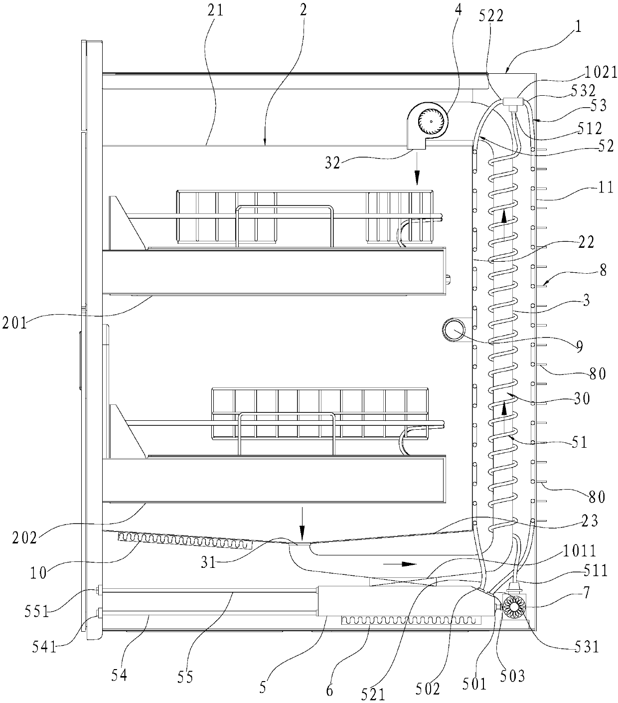
[0029] Such as Figure 1~4 As shown, a high-efficiency disinfection cabinet includes a box body 1 and an inner container 2 arranged in the box body 1. An upper cabinet 201 and a lower cabinet 202 for placing tableware to be sterilized are installed in the inner container 2. In this embodiment, Among them, the upper cabinet 201 and the lower cabinet 202 are both drawer type.
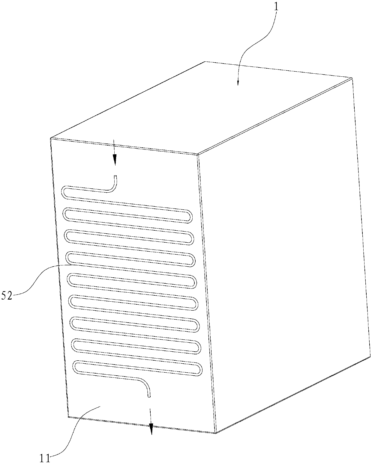
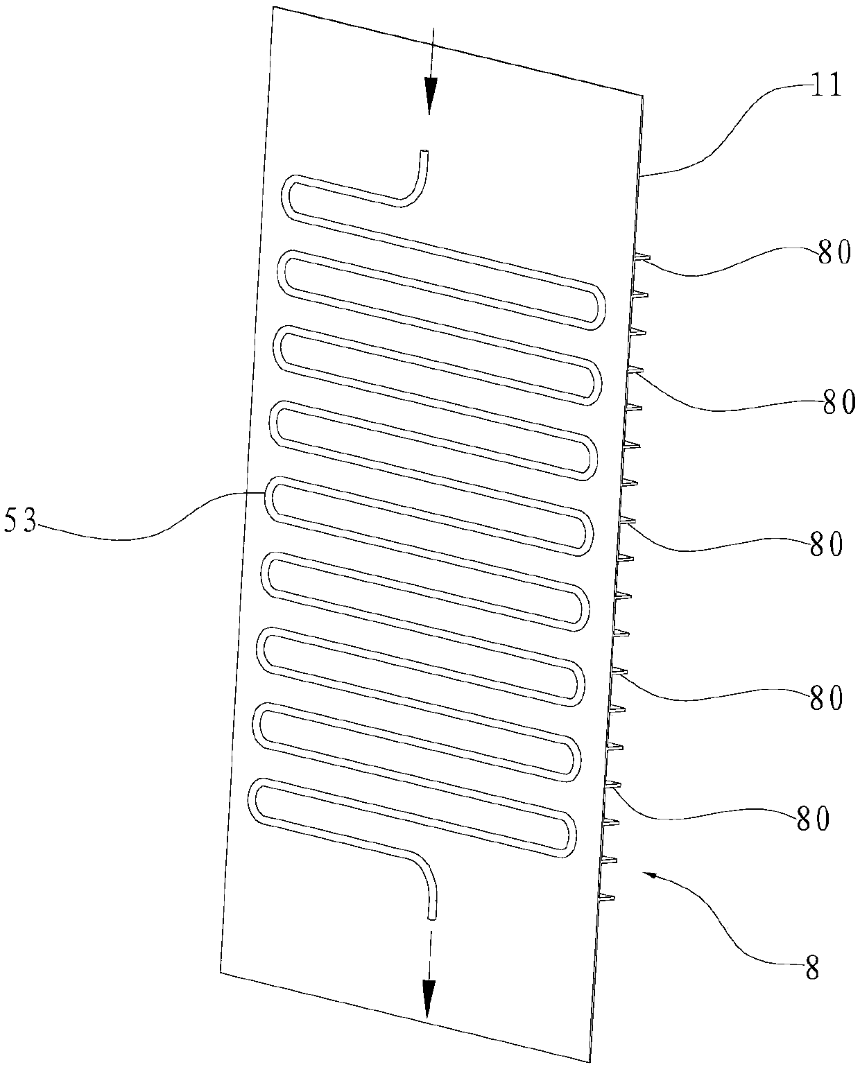
[0030] Further, the above-mentioned box body 1 is also provided with an airflow passage 30, the airflow passage 30 has an air inlet 31 and an air outlet 32, and the air inlet 31 and the air outlet 32 are respectively communicated with the above-mentioned inner tank 2, and the inner tank 2 The airflow can enter the airflow channel 30 through the air inlet 31 , and then flow back from the airflow channel 30 to the inner container 2 through the air outlet 32 . The air flow channel 30 can be realized in many ways. In this embodiment, an air flow pipe 3 is arranged in the gap between the back plate 22 of ...
Embodiment 2
[0048] Such as Figure 5 As shown, different from Embodiment 1, in this embodiment, the winding density of the outlet pipe 51 on the temperature-changing pipe 3 is sparse at the bottom and dense at the top. The hot water has the highest temperature when it just flows out of the water tank 5. During the flow along the outlet pipe 51, the temperature of the water gradually decreases due to the heat transfer with the temperature-changing pipe 3. In this embodiment, the winding of the outlet pipe 51 on the temperature-changing pipe 3 The density is set to be sparse at the bottom and dense at the top, so that the outlet pipe 51 can evenly heat the temperature-changing pipe 3
Embodiment 3
[0050] Such as Figure 6 As shown, the difference from Embodiment 1 is that in this embodiment, the ultraviolet lamp 9 is rotatably arranged in the inner tank 2 , so that the irradiation dead angle of the ultraviolet lamp 9 can be minimized. A spoiler fan 101 is installed on the inner side of the back plate 22 of the inner tank 2. Due to the effect of the temperature-changing channel 30, the airflow in the inner tank 2 flows from top to bottom, and the spoiler fan 101 can disturb the inner tank in the left and right directions. 2, thereby forming a three-dimensional circulating airflow field in the inner tank 2, so that gases such as ozone and steam can be quickly and evenly distributed in the inner tank 2.
[0051]Further, an installation base 103 is fixed on the inner surface of the back plate 22 of the inner container 2, a spoiler motor 104 is installed on the installation base 103, and the ultraviolet lamp 9 is arranged horizontally in the inner container 2 along the left ...
PUM
 Abstract
Description
Claims
Application Information