


Quick Research
Generate reliable direction feasibility study reports for your R&D in just a few steps.

Technical Q&A
Discover and master advanced knowledge NOW. Basics, ideas, possibilities, all at once.

Find Solutions
As an expert in R&D theories, this can generate solutions to your technical problems instantly.

Evaluate Feasibility
Analyze your overall solution with one click, know your potential R&D risks in advance.

Monitor Landscape
Get weekly tech updates, stay abreast of the latest tech innovations and key insights.
a machining table
A technology of machining and turning over tables, which is applied in metal processing equipment, metal processing mechanical parts, manufacturing tools, etc., can solve the problems of narrow work table space, time-consuming and labor-intensive installation and disassembly, and troublesome operation, so as to improve the operation and installation. improve the cleanliness effect, avoid slag splashing
- Summary
- Abstract
- Description
- Claims
- Application Information
AI Technical Summary
Problems solved by technology
Method used
Image

Examples
Embodiment 1
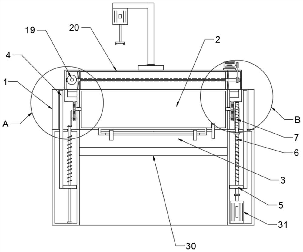
[0024] see Figure 1-6 , in the embodiment of the present invention, a kind of mechanical processing table, comprises working table 1, turning table 2 and enclosure mechanism; Said turning table 2 is the turning board that is nested in working table 1 and can turn over 180 degrees, and turning table 2. The upper end surface is a horizontal plane, which can be used as an assembly operation table. The lower end surface of the turning table 2 is provided with a clamping mechanism 3. The clamping mechanism 3 is used to clamp the workpiece and can be used as a cutting processing workbench; the turning table 2 The left side is rotationally connected with the workbench 1 through the left rotating shaft 13, and the right side of the turning table 2 is rotationally connected with the workbench 1 through the right rotating shaft 12.
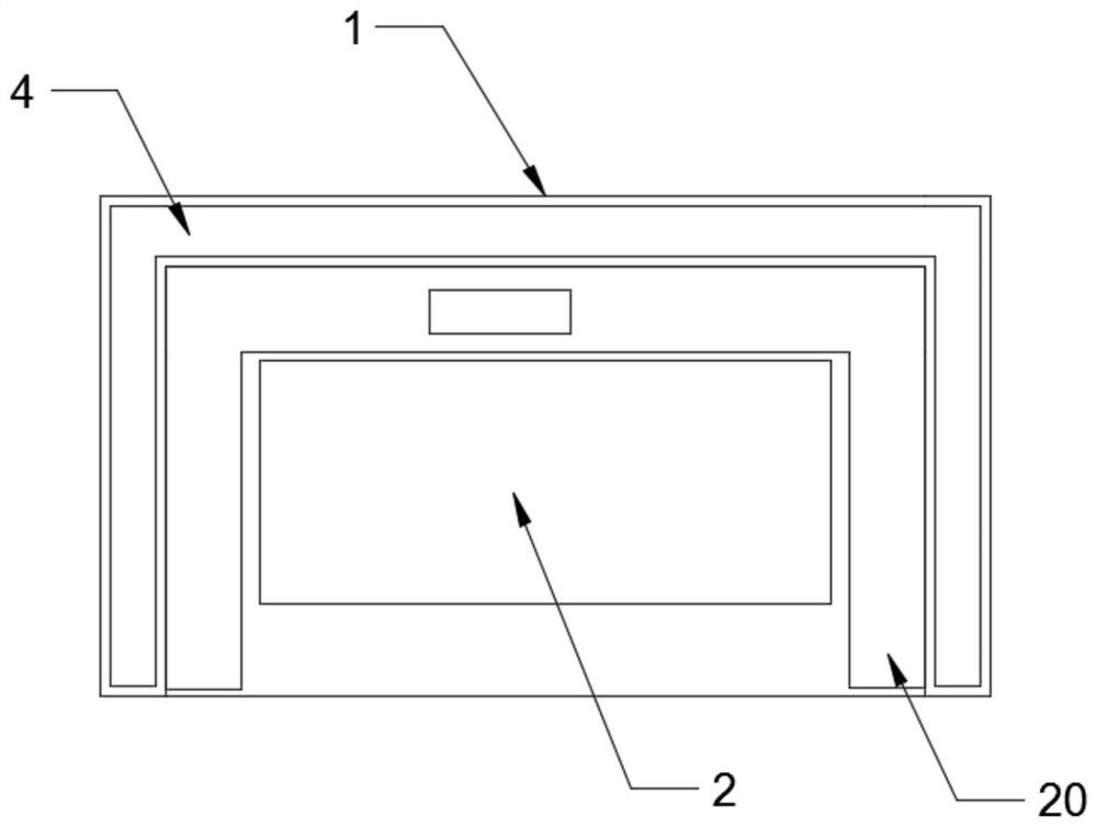
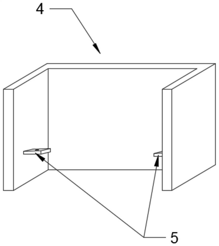
[0025] The fence mechanism includes a fence 4, the fence 4 is a three-sided fence formed by vertical plates on three sides, the fence 4 is nested in the w...
Embodiment 2
[0028] The difference between this embodiment and Embodiment 1 is that: a debris cleaning mechanism is provided above the workbench 1, and the debris cleaning mechanism includes a storage box 20, which is arranged on the inside of the surrounding baffle plate 4, and the storage box 20 is an inner opening. The hollow box body; described holding box 20 is provided with brush roll 19, and brush roll 19 is connected with moving block 22 by rotating shaft 21 rotations, and moving block 22 is in the holding box 20 and is slidably connected with holding box 20; The moving block 22 runs through and is threadedly connected with a transverse screw rod 23, which is rotationally connected with the inner wall of the housing box 20; 25 drives the horizontal screw rod 23 to rotate, and then drives the brush roller 19 to move horizontally back and forth, so that the brush roller 19 can sweep the upper surface of the turning table 2 to clean the debris; the rotating shaft 21 is sleeved and fixe...
PUM
 Abstract
Description
Claims
Application Information
 - R&D Engineer
- R&D Manager
- IP Professional
- Industry Leading Data Capabilities
- Powerful AI technology
- Patent DNA Extraction
Browse by: Latest US Patents, China's latest patents, Technical Efficacy Thesaurus, Application Domain, Technology Topic, Popular Technical Reports.
© 2024 PatSnap. All rights reserved.Legal|Privacy policy|Modern Slavery Act Transparency Statement|Sitemap|About US| Contact US: help@patsnap.com