
Mechanical processing platform for pipe fitting processing

A technology for machining platforms and pipe fittings, applied in the direction of manufacturing tools, workpiece clamping devices, etc., can solve the problems of reduced processing efficiency, increased production cost, inconvenient use, etc., and achieve the goal of improving processing efficiency, reducing labor intensity, and reducing production costs Effect

Active Publication Date: 2020-06-02
HUAIBEI ZHIHUAI TECH CO LTD
View PDF10 Cites 1 Cited by
  • Summary
  • Abstract
  • Description
  • Claims
  • Application Information

AI Technical Summary

Problems solved by technology

[0003] Common machining platforms for processing pipe fittings are inconvenient to use. For example, a machining platform for tubular billets in China (Application No.: 201611031635.3) includes a machining platform and a clamping device. Hydraulic cylinder, the piston rod on the hydraulic cylinder is fixedly connected with the left surface of the hinge seat, the hinge seat slides on the upper surface of the guide table, the right end of the hinge seat is connected with one end of the hinge arm through the hinge shaft, and the hinge arm The other end is rotatably connected to the left end of the pressing rod through a hinge shaft, and a supporting seat is fixedly arranged on the upper surface of the processing platform. The right end of the processing platform is also fixedly equipped with a clamping device, which clamps and fixes the right part of the tubular steel billet through an upper clamp and a lower clamp inside the clamping device.
The invention has the advantages of simple structure, convenient installation and easy operation, and can be widely used in mechanical processing technology, especially in the mechanical processing of tubular billets. However, in the process of use, it is necessary to manually push the pipe fittings to move, which not only increases the labor intensity of workers, but also takes time. It is laborious, resulting in a reduction in processing efficiency, which increases the production cost of the factory and brings great inconvenience to the processing of pipe fittings

Method used


Image

  • Mechanical processing platform for pipe fitting processing
  • Mechanical processing platform for pipe fitting processing
  • Mechanical processing platform for pipe fitting processing

Examples


Embodiment 1

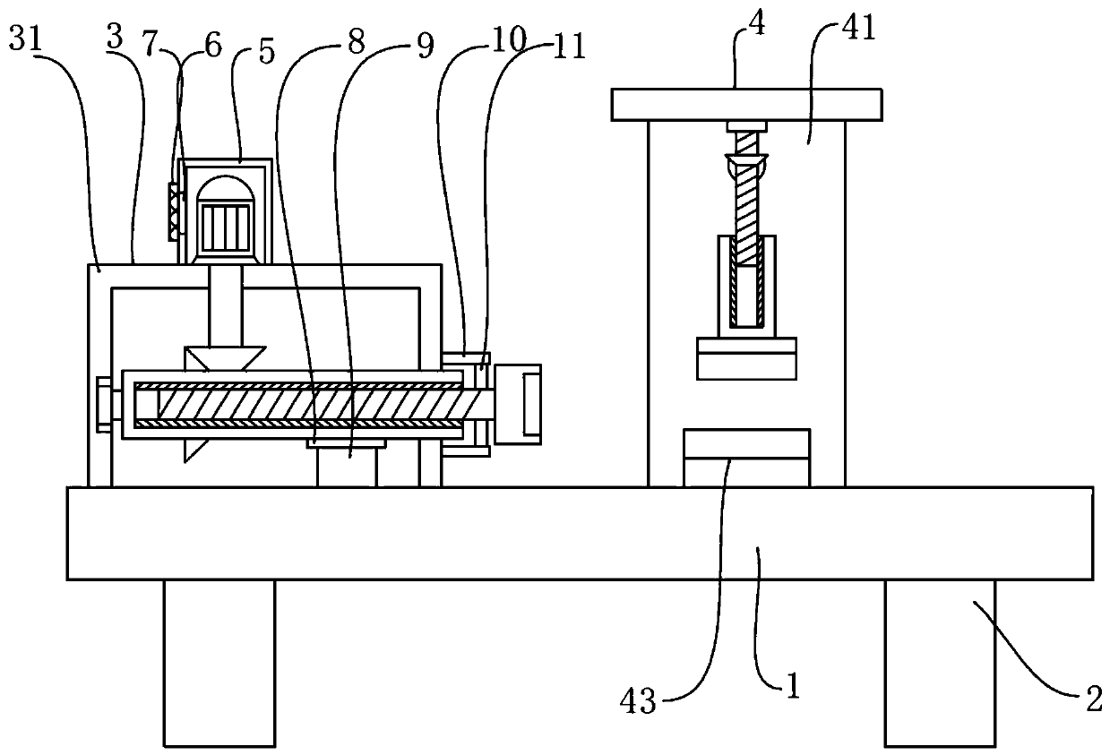
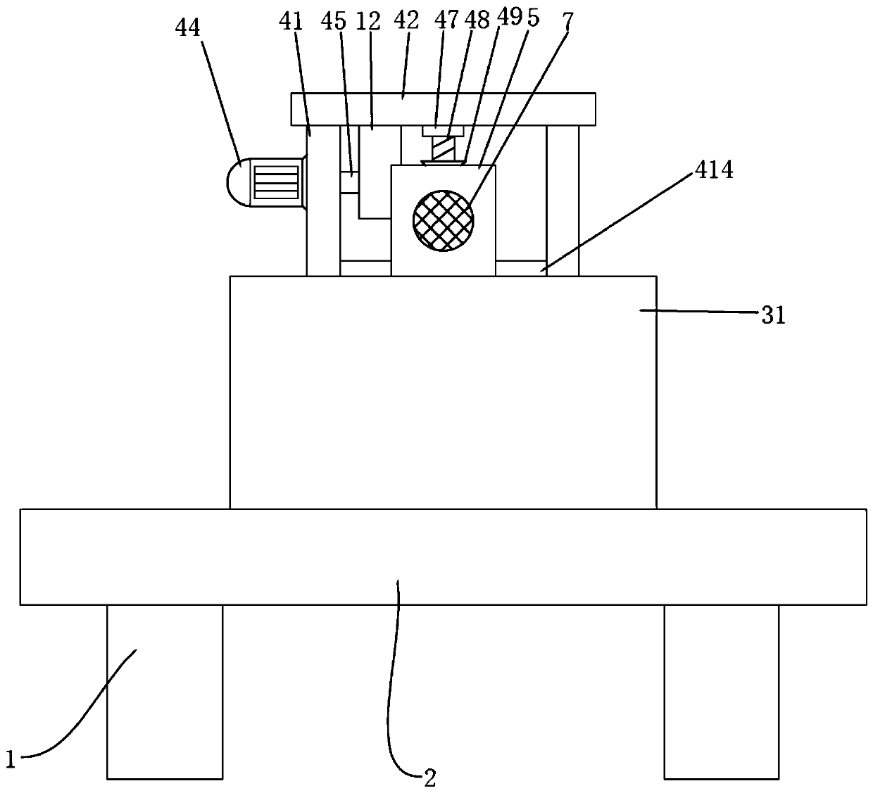
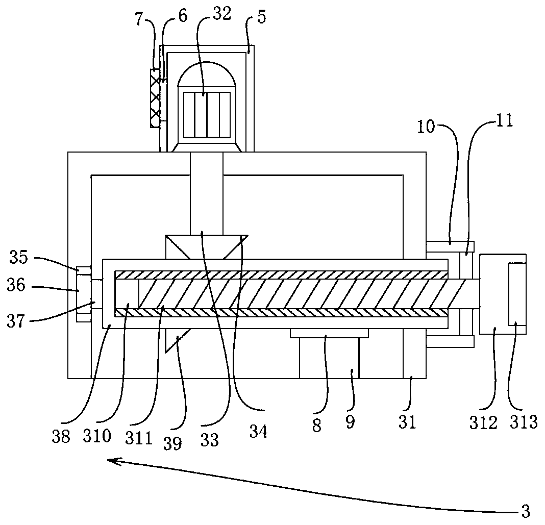
[0025] By cooperating with the third threaded groove 415 and the third threaded shaft 416, the effect of facilitating the replacement of the second clamping block 417 is played. The second clamping block 417 can be replaced according to the size of the pipe diameter, and the rotating motor 44 is started, and the rotating motor 44 drives the third gear 46 to rotate by rotating shaft 45, and the third gear 46 drives the fourth gear 49 that meshes with it to rotate, and the fourth gear 49 drives the second threaded shaft 48 to rotate, because the second threaded shaft 48 and the second thread groove 411 is threaded, and the clamping shaft 410 is limited by the chute 412 and the slider 413, so that the clamping shaft 410 drives the second clamping block 417 to move downward, and the first clamping block 43 and the second clamping block 417 Cooperate with each other to clamp the pipe fittings.

Embodiment 2

[0027] Put the pipe between the first clamping block 43 and the second clamping block 417, the left end of the pipe extends into the inside of the fixing groove 313, then start the rotating motor 44, and the rotating motor 44 drives the third gear 46 to rotate through the rotating shaft 45 , the third gear 46 drives the second threaded shaft 48 to rotate through the fourth gear 49, because the second threaded shaft 48 is threadedly connected with the second threaded groove 411, and the clamping shaft 410 is limited by the chute 412 and the slider 413, so that The clamping shaft 410 drives the second clamping block 417 to move downward, and the first clamping block 43 cooperates with the second clamping block 417 to clamp the pipe, and then process the pipe. , the rotating motor 44 drives the rotating shaft 45 to rotate in reverse, so that the clamping shaft 410 drives the second clamping block 417 to move upward, and then starts the driving motor 32, and the driving motor 32 dr...


PUM


Abstract

The invention discloses a mechanical processing platform for pipe fitting processing. The mechanical processing platform comprises an operation table, wherein supporting legs are fixedly connected tofour corners at the bottom of the operation table; a pushing device is arranged on the left side of the top of the operation table; a clamping device is arranged on the right side of the top of the operation table; the pushing device comprises a housing; and the bottom of the housing is fixedly connected with the top of the operation table. According to the mechanical processing platform disclosedby the invention, the operation table, the supporting legs, the pushing device, the clamping device, a protecting housing, a heat dissipation tank, a dust screen, an anti-friction mat, a supporting block, a limiting block, a connecting block, a fixed block, a through tank and a third bearing mutually cooperate, so that the problem that a familiar mechanical processing platform for pipe fitting processing is inconvenient to use is solved; and in the pipe fitting processing course, a moving manner of automatically pushing the pipe fitting is adopted, so that the pipe fittings do not need to bemanually pushed, the labor intensity of workers is reduce, time and labor are saved, the processing efficiency is improved, the production cost of the plant is reduced, and great convenience is brought to pipe fitting processing.

Description

technical field [0001] The invention relates to the technical field of mechanical processing, in particular to a mechanical processing platform for processing pipe fittings. Background technique [0002] Machining is a process of changing the shape or performance of workpieces with processing machinery. According to the temperature state of the processed workpiece, it can be divided into cold processing and hot processing. Generally, it is processed at room temperature and does not cause chemical or phase changes of the workpiece, which is called cold processing. Generally, processing at higher or lower than normal temperature will cause chemical or phase changes of the workpiece, which is called thermal processing. Cold processing can be divided into cutting processing and pressure processing according to the difference in processing methods. Thermal processing commonly includes heat treatment, forging, casting and welding. The machining process is the step of manufactur...

Claims


Application Information

Patent Timeline
IPC IPC(8): B25B11/00
CPCB25B11/00
Inventor 耿洪玲任晨
Owner HUAIBEI ZHIHUAI TECH CO LTD
Learn More