Driving control device for remote controlled helicopter

A technology for helicopters and equipment, applied in remote control aircraft, non-electric variable control, motor vehicles, etc., can solve problems such as difficulty in quickly correcting posture, overturning, and difficulty in steering a remote control helicopter.

Active Publication Date: 2020-06-02
FUTABA CORPORATION
View PDF8 Cites 0 Cited by
  • Summary
  • Abstract
  • Description
  • Claims
  • Application Information

AI Technical Summary

Problems solved by technology

Therefore, the steering of the RC helicopter becomes difficult
Then, if the fuselage 11a of the remote control helicopter 11

Method used


Image

  • Driving control device for remote controlled helicopter
  • Driving control device for remote controlled helicopter
  • Driving control device for remote controlled helicopter

Examples


Embodiment Construction

[0022] Hereinafter, embodiments will be described in detail with reference to the accompanying drawings.

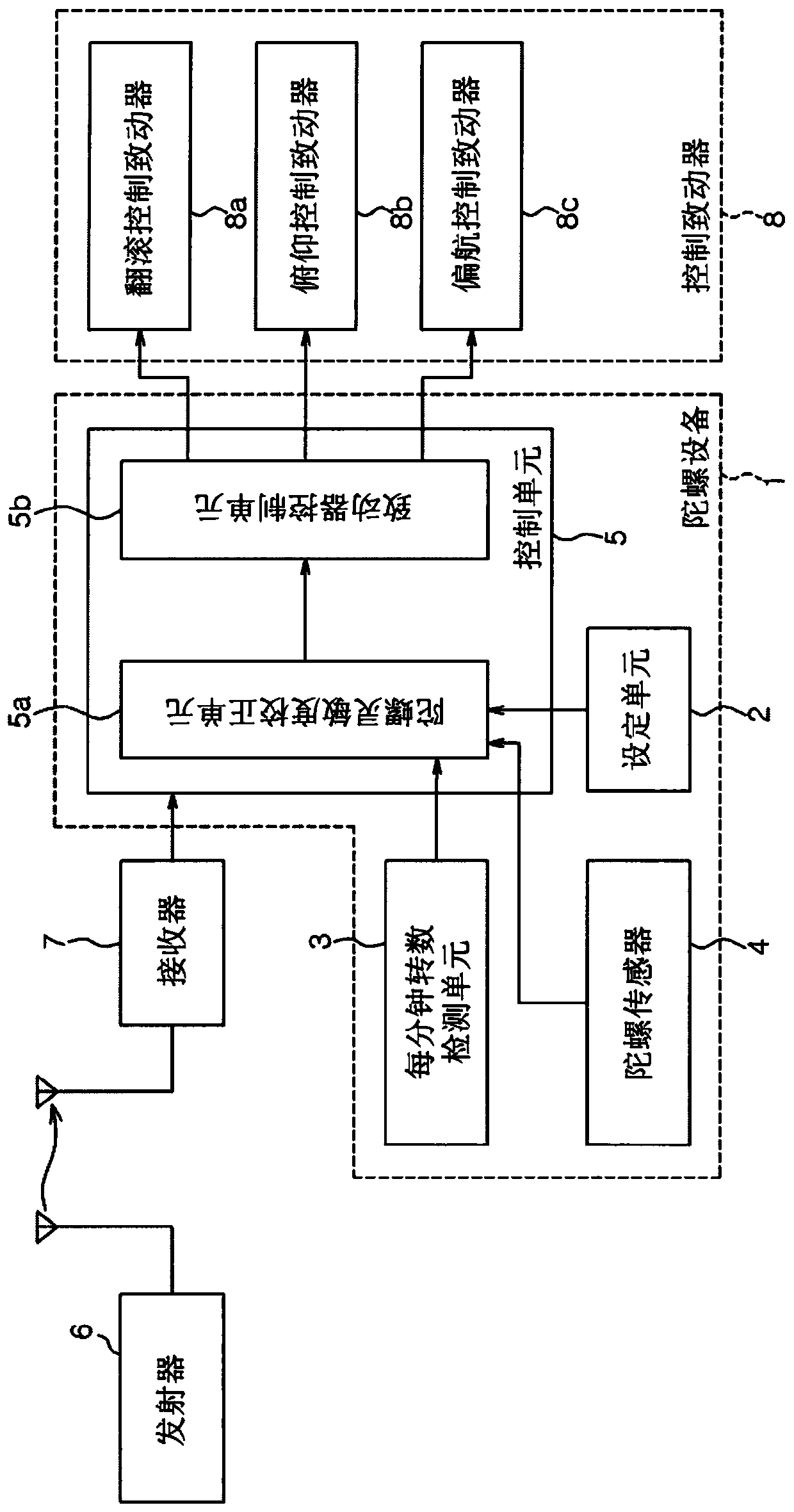
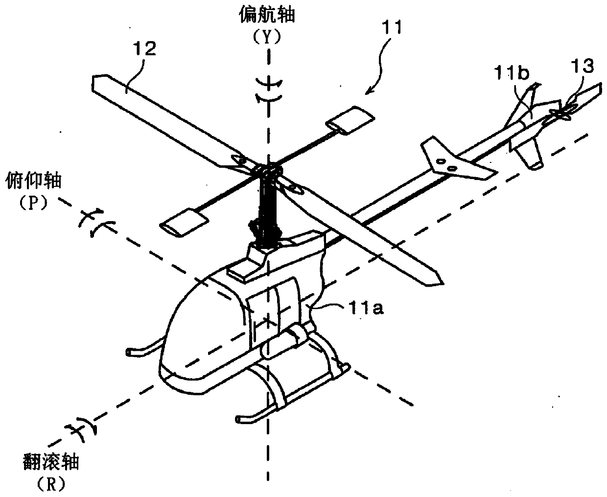
[0023] Such as figure 1 As shown, in addition to the gyro function, the gyro device 1 also has a governor function and a flight condition (flight mode) function. The gyro device 1 is configured as a drive control device including a setting unit 2 , an RPM detection unit 3 , a gyro sensor 4 , and a control unit 5 . Such as image 3 As shown, the gyro apparatus 1 is mounted on, for example, a fuselage 11 a of a remote control helicopter 11 .

[0024] The governor function is a function for controlling the RPM of the main rotor 12 to a preset RPM.

[0025] The flight condition function is a function to designate a mode according to the flight state of the remote control helicopter 11 (for example, hovering, circular flight, rolling flight, automatic rotation during landing, etc.). For each mode, the RPM of the main rotor 12, the movement amount of the control shaft and t...


PUM


Abstract

A driving control device for a remote controlled helicopter includes an rpm detection unit that detects an rpm of a main rotor, a gyro sensor that detects angular velocities of control axes includingroll, pitch and yaw axes, and a control unit that generates a control signal of a control actuator for controlling movements of the control axes based on the angular velocities detected by the gyro sensor and a steering signal sent from a transmitter. The control unit has information on the gyro sensitivities of the control axes and information on a set rpm of the main rotor which are preset for each of the flight states of the remote controlled helicopter, and corrects the gyro sensitivities based on a difference between the set rpm corresponding to a selected flight state among the flight states and an rpm of the main rotor detected by the rpm detection unit.

Description

technical field [0001] The present disclosure relates to a driving control device for a remote-controlled helicopter, such as a model helicopter, an aerial photography helicopter, a crop spraying helicopter, and the like. Background technique [0002] For example, remote control helicopters 11 such as model helicopters basically have image 3 construction shown. The driving of the remote control helicopter 11 is controlled by a main rotor 12 installed on the fuselage 11a and a tail rotor 13 installed on the tail 11b. The main rotor 12 generates a lifting force by rotating, and controls the ascending / descending, forward / backward, and left / right driving of the remote control helicopter 11 by adjusting a pitch angle. The tail rotor 13 has a function of canceling the reaction torque caused by the rotation of the main rotor 12 and controlling the horizontal rotation of the remote control helicopter 11 . [0003] However, in the remote-controlled helicopter 11, as disclosed in J...

Claims


Application Information

Patent Timeline
IPC IPC(8): B64C27/56G05D1/10
CPCB64C27/56G05D1/101B64U10/10B64U2201/20B64C27/12B64C39/024B64C2203/00G05D1/0858B64C27/06B64C27/57B64U2201/00G05D1/0816G05D1/0011
Inventor 田中昌广
Owner FUTABA CORPORATION
Why Eureka
Try Eureka