Zero-clearance rear-mounted mold slip form paver

A slip-form paver and zero-gap technology, applied in roads, road repairs, roads, etc., can solve problems such as restricting the application prospects of slip-form construction technology, affecting the reliability of oil cylinders, and not having construction conditions, etc., achieving compact structure, The effect of stable center of gravity structure and reasonable length design

Pending Publication Date: 2020-06-02
JIANGSU SIMING ENG MACHINERY
View PDF0 Cites 3 Cited by
  • Summary
  • Abstract
  • Description
  • Claims
  • Application Information

AI Technical Summary

Problems solved by technology

[0003] There are obvious defects in the large mid-mounted slipform paver: 1) The paving mold is set between the crawlers on both sides of the crawler travel device, so the width of the subgrade is required to be greater than the width of the road to be constructed, but in rural roads, mountainous There are no construction conditions for construction projects with widened subgrades, which restricts the application prospect of slipform construction technology in low-grade highways with limited subgrade width and many curves
2) Adjust the thickness and flatness of the pavement through the lifting of the lifting column device, the precision is not high, which affects the quality of the road surface
3) The vibration device is directly driven up and down through the vertically arranged oil cylinder to achieve height adjustment, and the oil cylinder is very close to the cement slurry tank, and the cement material is easy to enter the piston rod of the oil cylinder, which affects the reliability of the oil cylinder; and the cement material is easy to enter the guide rail matched with the oil cylinder inside, causing stuck

Method used


Image

  • Zero-clearance rear-mounted mold slip form paver
  • Zero-clearance rear-mounted mold slip form paver
  • Zero-clearance rear-mounted mold slip form paver

Examples


Embodiment Construction

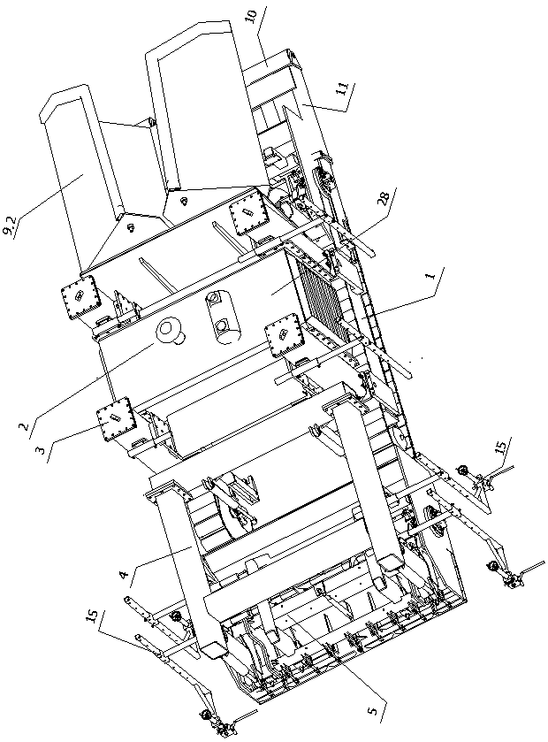
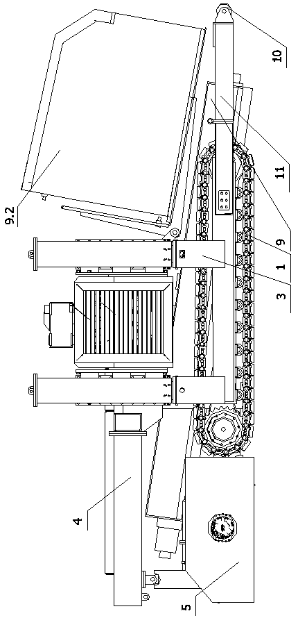
[0036] Such as Figure 1-7 As shown, the present invention includes a main engine 2 and a rear mold paving device 5. The main engine 2 includes a crawler walking device 1, a lifting column device 3 and an engine assembly 28. The rear side of the lifting column device 3 is connected with a square frame platform 4. Put mold paving device 5 and be arranged on the below of square frame platform 4.

[0037] As a further description of this embodiment, the width of the crawler traveling device 1 is smaller than that of the rear mold paving device 5, so that the present invention can adapt to the construction of a road surface as wide as the roadbed.

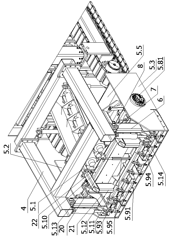
[0038] The rear mold paving device 5 includes a mold frame 5.1, and the mold frame 5.1 includes a left side plate 5.2 and a right side plate 5.3, and a front baffle plate 5.5 and a middle part arranged in front and rear are arranged between the left side plate 5.2 and the right side plate 5.3. The baffle frame 20, the middle baffle fr...


PUM


Abstract

The invention discloses a zero-clearance rear-mounted mold slip form paver, and relates to the technical field of engineering machinery. The zero-clearance rear-mounted mold slip form paver comprisesa main machine and a rear mold paving device, the main machine comprises a crawler walking device, a lifting stand column device and an engine assembly. The rear side of the lifting stand column device is connected with a square frame platform. The rear mold paving device is arranged below the square frame platform; the rear mold paving device is connected with the square frame platform through anoil cylinder lifting device, the oil cylinder lifting device is used for driving the rear mold paving device to ascend and descend, and a leveling sensor is further installed on the paver and used for controlling ascending and descending of the lifting stand column device and/or the oil cylinder lifting device according to detection signals. The paving thickness of the forming mold can be independently controlled through cooperation of the leveling sensor and the lifting oil cylinder, and the leveling precision and the road surface flatness are improved.

Description

technical field [0001] The invention relates to the technical field of engineering machinery, in particular to a zero-gap post-mold sliding form paver. Background technique [0002] At present, in the construction of cement pavement, the slip-form construction technology has been widely used. Compared with the traditional artificial prefabrication method, slip form construction has the advantages of high construction efficiency, beautiful outline and reliable construction quality. Slipform construction can complete the paving of cement pavement at one time, which greatly reduces labor costs and shortens the construction period. Slipform paver usually adopts mid-mounted paving, because of its good paving effect and stable structure, it has been widely used in high-grade highways and large squares and other projects. [0003] There are obvious defects in the large mid-mounted slipform paver: 1) The paving mold is set between the crawlers on both sides of the crawler travel d...

Claims


Application Information

Patent Timeline
Patent Type & Authority Applications(China)
IPC IPC(8): E01C19/48
CPCE01C19/486
Inventor 赵国普黄烨蔡峰王吉卞晓峰陆晨蔡志浦潘登超张洪昌李俊
Owner JIANGSU SIMING ENG MACHINERY
Why Eureka
Try Eureka