Construction method for quickly and non-destructively breaking pile heads

A construction method and pile head technology, applied in sheet pile wall, foundation structure engineering, construction, etc., can solve the problems of easy inclined connection, dust pollution, labor consumption, etc., to avoid friction interference, ensure advanced nature, and support equipment. less effect

Inactive Publication Date: 2020-06-02
SHANDONG LUQIAO CONSTR
View PDF8 Cites 6 Cited by
  • Summary
  • Abstract
  • Description
  • Claims
  • Application Information

AI Technical Summary

Problems solved by technology

[0003] After the cast-in-situ pile is constructed, the pile head needs to be removed. Generally, large-scale machinery must not be used to remove the pile head concrete, so as not to disturb the pile body concrete. This requires manual use of pneumatic picks to remove the pile head. However, the existing pile head construction structure is not conducive to pile head separation.
The first is that the construction speed is slow, which consumes a lot of manpower, which seriously affects the progress of the project and increases the construction cost; the second is that when the internal casing and the steel bar are socketed, the center alignment cannot be guaranteed, and the connection is easy to be inclined. Cause interference and affect the overall lifting of the pile head; thirdly, the process of artificial jack removal is accompanied by noise and dust pollution, which is not conducive to environmental protection and workers' occupational health
Therefore, the construction structure and methods still need to be improved

Method used


Image

  • Construction method for quickly and non-destructively breaking pile heads
  • Construction method for quickly and non-destructively breaking pile heads
  • Construction method for quickly and non-destructively breaking pile heads

Examples


Embodiment Construction

[0029] In order to make the object, technical solution and advantages of the present invention more clear, the present invention will be further described in detail below in conjunction with specific examples. It should be understood that the specific examples described here are only used to explain the present invention, not to limit the present invention.

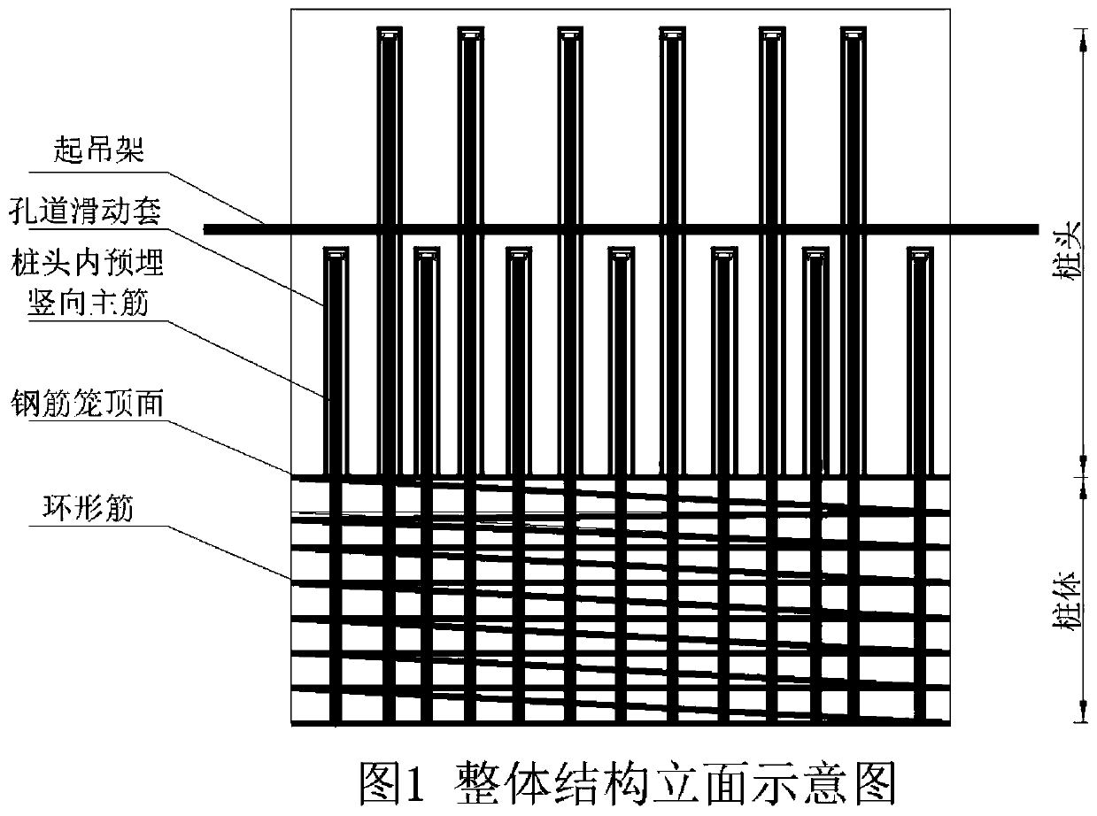
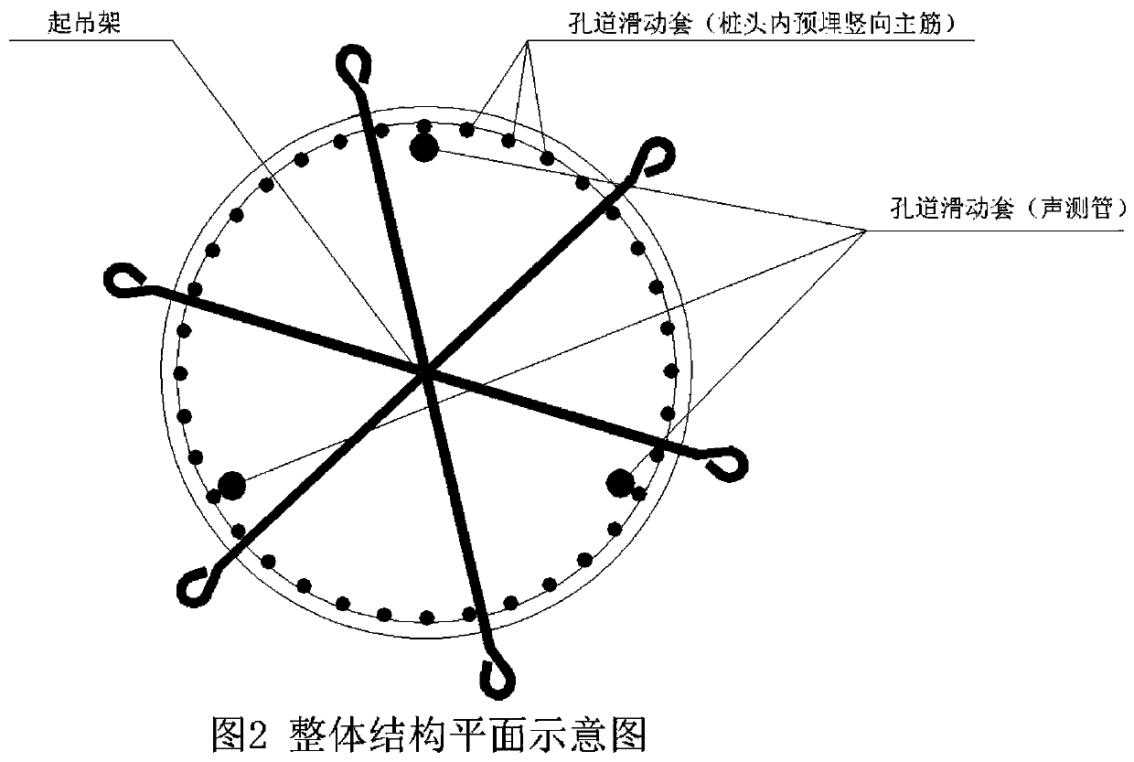
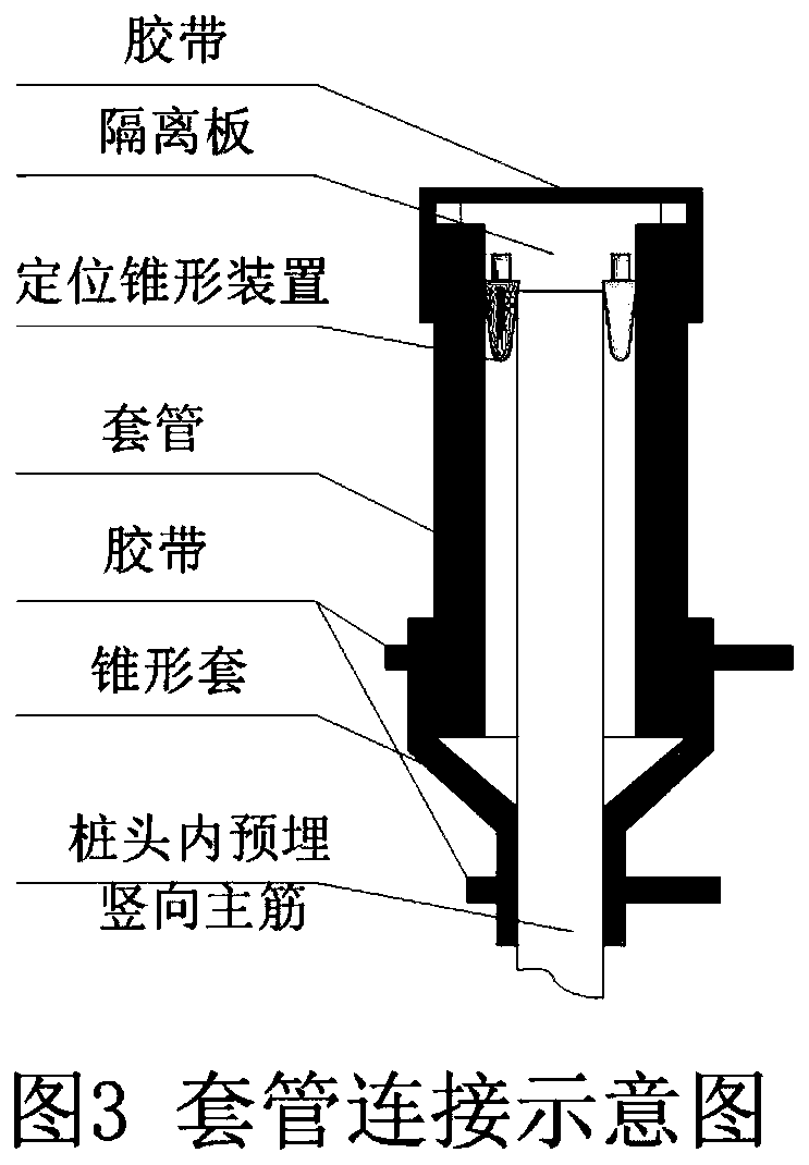
[0030] see Figure 1-5 , a construction method for quickly and non-destructively destroying a pile head, including a pile body. The interior of the pile body is provided with a reinforcement cage, the vertical main reinforcement reserved in the pile head of the reinforcement cage and the outer surface of the acoustic tube are provided with tunnel sliding sleeves, and the upper and lower ends of the tunnel sliding sleeves are respectively provided with isolation plates and The tapered sleeve is bonded and sealed with adhesive tape. The vertical main reinforcement reserved in the pile head of the steel cage is not less tha...


PUM


Abstract

The invention discloses a construction method for quickly and non-destructively breaking pile heads. In the construction method, a pile body is included. A reinforced cage is arranged inside the pilebody; vertical main reinforcements are reserved in a pile head of the reinforced cage; a pore passage sliding sleeve is arranged on the outer surface of a sound measuring pipe; an isolation plate anda tapered sleeve are separately arranged at the upper and lower ends of the pore passage sliding sleeve; the upper and lower ends of the pore passage sliding sleeve are bonded and sealed with an adhesive tape; a lifting frame (the whole pile head is used as a marking rod before lifting) is arranged at a position where the vertical main reinforcements reserved in the pile head of the reinforced cage are not smaller than 30 cm from the top surface of the reinforced cage; and a concrete pouring pile head is within the range of the vertical main reinforcements reserved in the pile head of the reinforced cage. After the construction of the pile head is completed, a high-pressure water jet technology (also known as hydraulic breaking technology) is used for properly removing concrete from the lifting frame to the top surface of the reinforced cage, and finally the pile head is integrally hoisted by a crane, thereby completing the quick and non-destructive breaking of the whole pile head.

Description

technical field [0001] The invention relates to the field of building construction, in particular to a construction method for quick and non-destructive destruction of pile heads. Background technique [0002] In the field of construction engineering, more and more project engineering piles use concrete pouring piles. The construction technology of concrete pouring piles is mature, and the construction machinery is diverse, which can be applied to various geological conditions and various construction environments, and the pile quality is easy to control. [0003] After the cast-in-situ pile is constructed, the pile head needs to be removed. Generally, it is not allowed to use large-scale machinery to remove the pile head concrete, so as not to disturb the pile body concrete. This requires manual use of pneumatic picks to remove the pile head. However, the existing pile head construction structure is not conducive to pile head separation. . The first is that the constructio...

Claims


Application Information

Patent Timeline
Patent Type & Authority Applications(China)
IPC IPC(8): E02D9/00E02D9/02
CPCE02D9/00E02D9/02
Inventor 冯伟刘性帅宫德生张英霞李先重赵健杨立滕张晓春杨红艳李宁
Owner SHANDONG LUQIAO CONSTR
Why Eureka
Try Eureka