A three-dimensional tip clearance optical fiber bundle detection probe and its demodulation method

A technology of blade tip clearance and demodulation method, which is applied in the direction of engine testing, machine/structural component testing, measuring devices, etc., can solve the problem of insufficient reflection of aero-engine fault characteristics, poor real-time measurement effect, and measurement probe size. Large and other problems, to achieve the effect of simple structure, compact size and fast response speed

Active Publication Date: 2021-07-13
XI AN JIAOTONG UNIV
View PDF5 Cites 0 Cited by
  • Summary
  • Abstract
  • Description
  • Claims
  • Application Information

AI Technical Summary

Problems solved by technology

[0005] The traditional aero-engine blade tip clearance refers to the radial clearance from the blade tip surface to the inner surface of the case, which only has one dimension, and it is not comprehensive and sensitive enough to reflect the fault characteristics of the aero-engine. Response Characteristic Analysis of Typical Fault Characteristics” puts forward the concept of three-dimensional tip clearance of aero-engine blades. Through real-time monitoring including radial clearance, axial deflection angle, and circumferential deflection angle, the aero-engine’s performance can be obtained more comprehensively and intuitively. Fault information to realize real-time health monitoring of aero-engines; the patent with the authorized announcement number CN109141264B proposes a method and device for three-dimensional tip clearance demodulation, which provides an idea for the measurement of three-dimensional tip clearances of aero-engines, but the The demodulation method is too complicated, the real-time measurement effect is not good, and the size of the measurement probe is too large, it is difficult to apply to the actual installation process

Method used


Image

  • A three-dimensional tip clearance optical fiber bundle detection probe and its demodulation method
  • A three-dimensional tip clearance optical fiber bundle detection probe and its demodulation method
  • A three-dimensional tip clearance optical fiber bundle detection probe and its demodulation method

Examples


Embodiment Construction

[0059] The present invention will be described in detail below in conjunction with the accompanying drawings.

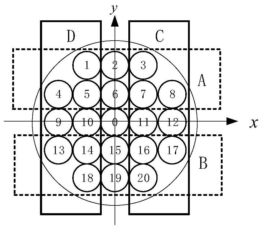
[0060] refer to figure 1 , a fiber bundle detection probe for three-dimensional blade tip clearance, comprising a transmitting fiber and a receiving fiber, the receiving fiber is arranged around the emitting fiber, one emitting fiber is arranged in the center, an even number of receiving fibers is arranged, the receiving fiber is about the end face of the emitting fiber The centerlines perpendicular to each other are distributed symmetrically, and the distance between optical fibers achieves the minimum sum of the distances between the transmitting fiber and all receiving fibers.

[0061] A grouped symmetrical optical fiber bundle probe for detecting three-dimensional blade tip clearance. The center of the optical fiber bundle detection probe is the transmitting optical fiber, and the receiving optical fiber is arranged around the emitting optical fiber. The receivin...


PUM


Abstract

The invention discloses a three-dimensional blade tip clearance optical fiber bundle detection probe and a demodulation method thereof, comprising a central transmitting optical fiber and surrounding receiving optical fibers, one transmitting optical fiber is arranged in the center, an even number of receiving optical fibers is arranged, and the receiving optical fiber With respect to the symmetrical distribution of the centerlines perpendicular to each other on the end faces of the transmitting fibers, the distance between the optical fiber and the optical fiber realizes the minimum sum of the distances between the transmitting fiber and all receiving fibers; Carry out left and right and up and down grouping, and use the difference in the received optical power of the receiving optical fiber at the symmetrical position of the different groups of the fiber optic probe to demodulate the three-dimensional tip clearance of the aeroengine, including the axial rotation angle, the circumferential rotation angle and the radial clearance, which is the three-dimensional tip clearance The detection provides a simple method, which helps to expand the methods of aero-engine health monitoring and fault diagnosis, and real-time demodulation of the three-dimensional tip clearance of aero-engines.

Description

technical field [0001] The invention belongs to the technical field of aero-engine manufacturing, and in particular relates to a three-dimensional blade tip clearance optical fiber bundle detection probe and a demodulation method thereof. Background technique [0002] Aeroengines are one of the most complex and precise high-speed rotating machines, and they work in harsh environments with high temperatures and high loads. In the field of civil aviation, engine failures account for 1 / 3 of all aircraft failures, and airlines all over the world will spend high maintenance costs on the maintenance of aeroengines every year. In military aviation, engine health monitoring and maintenance has become the primary factor affecting readiness and mission reliability. In order to ensure flight safety and reliability and reduce the maintenance cost of aero-engines, the development of aero-engine health monitoring technology is particularly important. [0003] Aeroengine blades are one o...

Claims


Application Information

Patent Timeline
Patent Type & Authority Patents(China)
IPC IPC(8): G01B11/14G01B11/26G01D5/353G01M15/02
CPCG01B11/14G01B11/26G01D5/3537G01M15/02
Inventor 张小栋刘洪成熊逸伟黄鑫徐志豪朱家浩
Owner XI AN JIAOTONG UNIV
Why Eureka
Try Eureka