
Liquid crystal display panel and preparation method thereof and liquid crystal display

A liquid crystal display panel and one-sided technology, applied in the direction of liquid crystal materials, chemical instruments and methods, instruments, etc., can solve the problems of narrow applicable temperature range of liquid crystal materials, failure of liquid crystals to work normally, increased startup time, etc., and achieve widening of the working temperature range , easy maintenance, increase heat dissipation effect

Active Publication Date: 2020-06-02
TCL CHINA STAR OPTOELECTRONICS TECH CO LTD
View PDF6 Cites 0 Cited by
  • Summary
  • Abstract
  • Description
  • Claims
  • Application Information

AI Technical Summary

Problems solved by technology

[0003] For liquid crystal displays used outdoors, it is necessary to meet the requirements of a wide operating temperature range. Due to the shortcomings of liquid crystal materials with a narrow applicable temperature range, ordinary liquid crystal displays cannot meet the needs of working outdoors, especially at low temperatures (below 0°C) Under the condition that the LCD does not work properly
In order to ensure that the liquid crystal display can work normally outdoors, the existing technology is to add a heating element to the liquid crystal display. In a low temperature (below 0°C) environment, the liquid crystal display can work normally at a suitable temperature through the heating effect of the heating element. This method has the disadvantages of increasing start-up time, increasing costs, and inconvenient maintenance

Method used


Image

  • Liquid crystal display panel and preparation method thereof and liquid crystal display
  • Liquid crystal display panel and preparation method thereof and liquid crystal display
  • Liquid crystal display panel and preparation method thereof and liquid crystal display

Examples


Embodiment Construction

[0044] The technical solutions in the embodiments of the present application will be clearly and completely described below in conjunction with the drawings in the embodiments of the present application. Apparently, the described embodiments are only some of the embodiments of this application, not all of them. Based on the embodiments in this application, all other embodiments obtained by those skilled in the art without making creative efforts belong to the scope of protection of this application.

[0045] In the description of the present application, it should be understood that the terms "center", "longitudinal", "transverse", "length", "width", "thickness", "upper", "lower", "front", " Orientation indicated by rear, left, right, vertical, horizontal, top, bottom, inside, outside, clockwise, counterclockwise, etc. The positional relationship is based on the orientation or positional relationship shown in the drawings, which is only for the convenience of describing the a...


PUM


Abstract

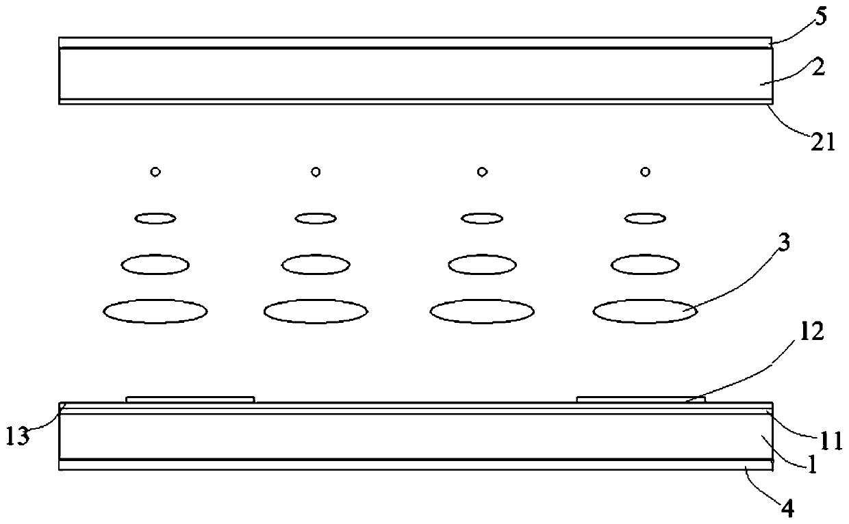
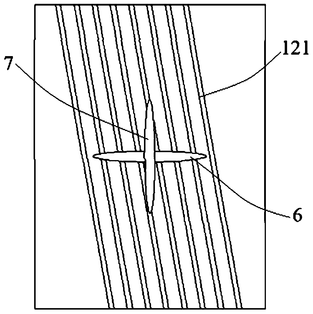
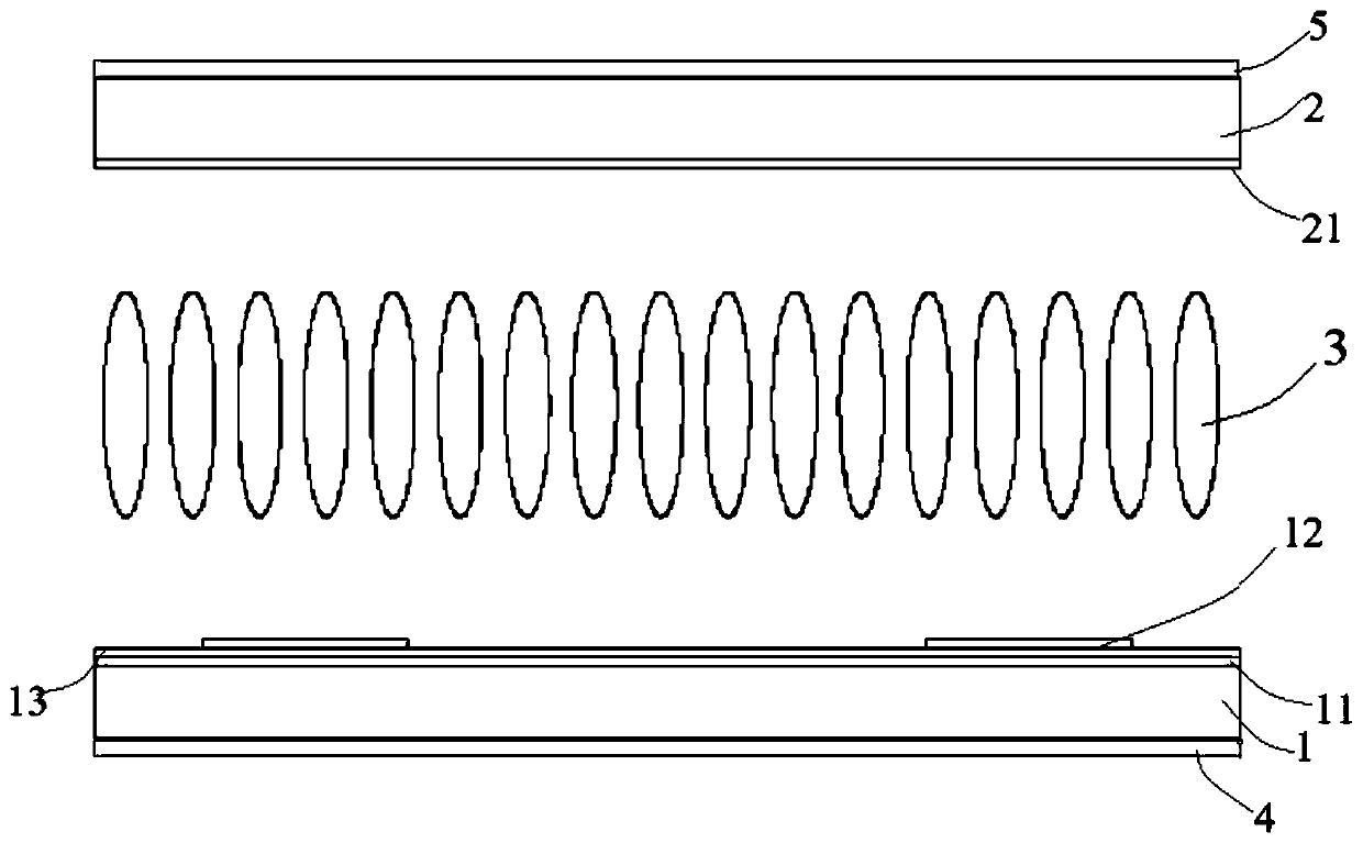
The invention discloses a liquid crystal display panel which comprises a first substrate provided with a first electrode layer and a second electrode layer, wherein an insulating layer is arranged between the first electrode layer and the second electrode layer, and a first alignment layer is arranged on the second electrode layer; a second substrate which is provided with a third electrode layer,wherein a second alignment layer is arranged on the third electrode layer; a liquid crystal layer which is clamped between the first alignment layer and the second alignment layer, and the liquid crystal layer is made of a double-frequency liquid crystal composition; a first polarizing layer which is arranged on one surface, far away from the liquid crystal layer, of the first substrate; and a second polarizing layer which is arranged on one surface, far away from the liquid crystal layer, of the second substrate. At a low temperature (below 0 DEG C), the liquid crystal display panel adopts high-frequency driving, so that the heating of the liquid crystal display panel is increased, the working temperature of the panel is increased, and extra heating elements are not needed. The liquid crystal display applying the liquid crystal display panel has a wide working temperature range, and is particularly suitable for outdoor use.

Description

technical field [0001] The present application relates to the field of display technology, in particular to a liquid crystal display panel, a preparation method thereof, and a display using the liquid crystal display panel. Background technique [0002] At present, liquid crystal display technology is the most widely used in the field of display, such as: LCD TVs, smart phones, computers, public display devices, vehicle display devices, etc. Liquid crystal display technology has deeply penetrated into modern life. Liquid crystal display has the advantages of light and thin, power saving, ideal display effect and so on. With the rapid development of liquid crystal display technology, liquid crystal displays are gradually moving from indoor display to outdoor display. [0003] For liquid crystal displays used outdoors, it is necessary to meet the requirements of a wide operating temperature range. Due to the shortcomings of liquid crystal materials with a narrow applicable te...

Claims


Application Information

Patent Timeline
IPC IPC(8): G02F1/1337G02F1/1343G02F1/137G02F1/139G02F1/1335C09K19/46
CPCG02F1/133707G02F1/134309G02F1/133528G02F1/137G02F1/1396C09K19/46G02F1/134372G02F1/133531G02F1/133753C09K2019/122C09K2019/3004C09K2019/301C09K2019/2042C09K2019/3083C09K19/3068C09K2019/2064C09K19/3066C09K2019/3027C09K19/12C09K19/2028C09K19/3003C09K2019/2078
Inventor 陈兴武
Owner TCL CHINA STAR OPTOELECTRONICS TECH CO LTD
Learn More