
Computer hardware durability test system

A computer hardware and test system technology, applied in the direction of detecting faulty computer hardware, computing, error detection/correction, etc., can solve the problems of not being able to get results quickly and intuitively, and there is no good solution for durability, and achieve results Intuitive, time-saving effects

Inactive Publication Date: 2020-06-02
ZHENGZHOU UNIVERSITY OF AERONAUTICS
View PDF0 Cites 1 Cited by
  • Summary
  • Abstract
  • Description
  • Claims
  • Application Information

AI Technical Summary

Problems solved by technology

[0004] As a commonly used computer hardware, the mouse has no good solution to the test of its durability, and the desired result cannot be obtained quickly and intuitively.

Method used


Image

  • Computer hardware durability test system
  • Computer hardware durability test system
  • Computer hardware durability test system

Examples


Embodiment 1

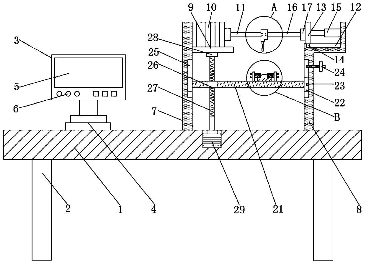
[0031] See Figure 1~6 In the embodiment of the present invention, a computer hardware durability performance test system includes a workbench 1. A number of support legs 2 are provided symmetrically at the lower end of the workbench 1, and a computer testing device 3 is provided on the left side of the upper end of the workbench 1. The test equipment 3 includes a rotating base 4, the upper end of the rotating base 4 is equipped with an equipment body 5, the lower front end of the equipment body 5 is provided with a number of control keys 6, and the equipment body 5 is installed with counting software and pressure monitoring software;

[0032] A left side plate 7 and a right side plate 8 are respectively provided on the right side of the upper end of the workbench 1, the left side plate 7 is located on the left side of the right side plate 8, and the upper right side of the left side plate 7 is provided with a mounting plate 9, and the mounting plate A motor 10 is installed on 9,...

Embodiment 2

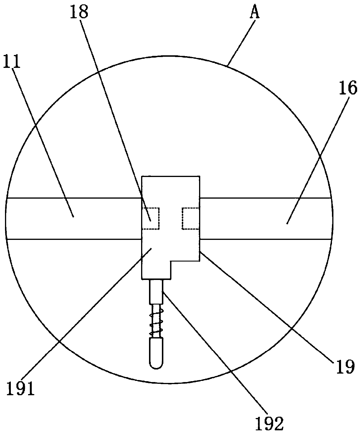
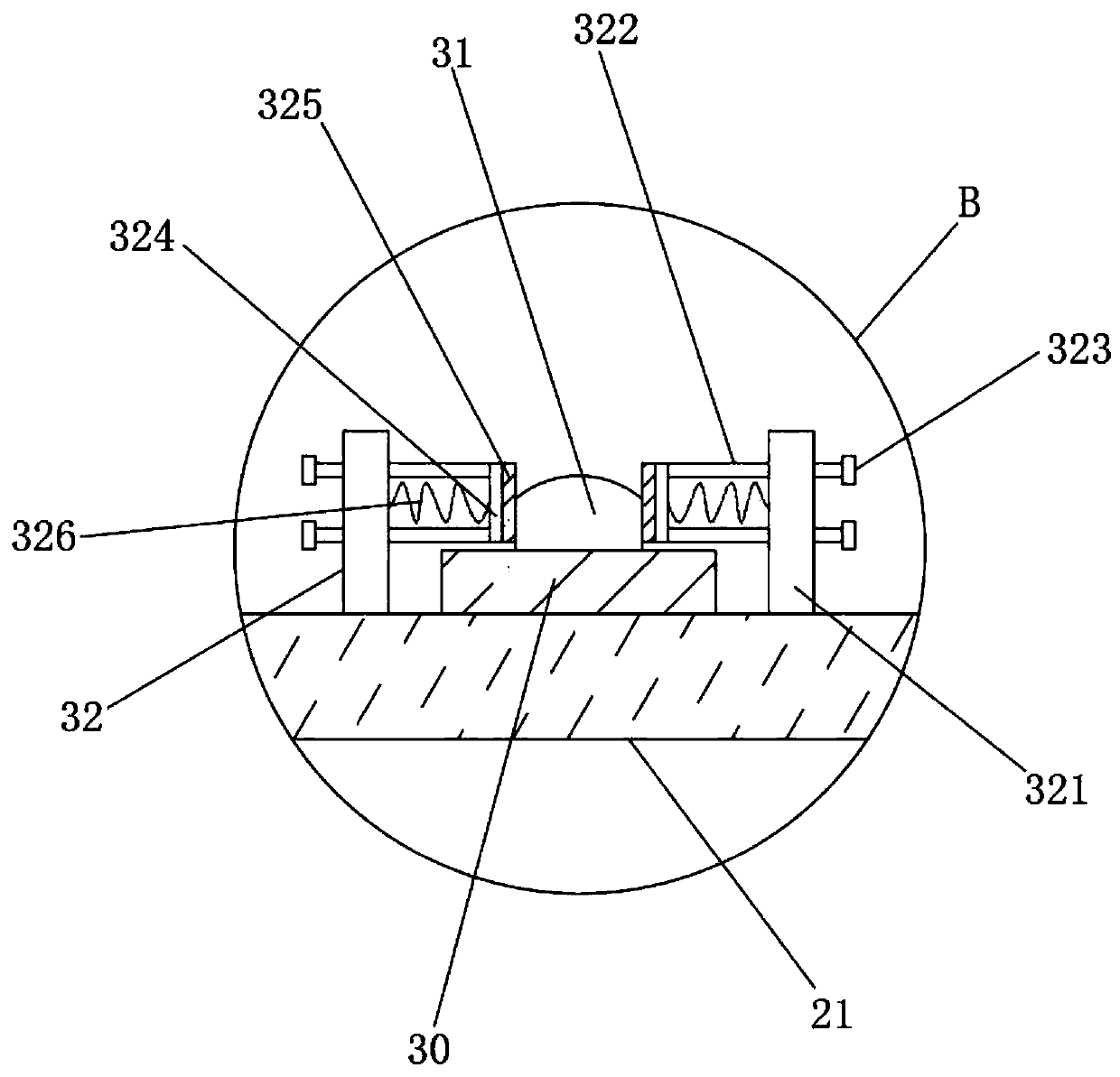
[0038] Such as Image 6 As shown, the difference between the second embodiment and the first embodiment is that: the first rotating shaft 11 and the second rotating shaft 16 are engaged with the second pressing structure 20. The second pressing structure 20 is composed of the second mounting block 201 and the second pressing member 202. The structure of the second block 201 and the second pressing part 202 is the same as the installation block one 191 and the first pressing part 192, and the second pressing part 202 is arranged on the right side of the lower end of the second installation block 201, and the bottom of the second pressing part 202 contacts the mouse body 31 Right click.

[0039] The working principle of the present invention is:

[0040] When the present invention is in use, first select the pressing structure 19 or pressing the structure 2 20 according to the actual test requirements (testing the left or right button of the mouse body 31). Take the pressing structur...


PUM


Abstract

The invention discloses a computer hardware durability testing system which comprises a workbench, and computer testing equipment is arranged at the left side of the upper end of the workbench. A leftside plate and a right side plate are arranged at the right side of the upper end of the workbench, the left side plate is located at the left side of the right side plate, and a mounting plate is arranged in the upper portion of the right side of the left side plate; a top sliding groove is formed in the upper end of the right side plate, a sliding plate is installed in the top sliding groove, the left side of the sliding plate is rotationally connected with a second rotating shaft through a first bearing seat, and a first pressing structure is clamped between the second rotating shaft and the first rotating shaft. According to the system, the pressing structure is driven by a first motor to press a left key or a right key of a mouse body, counting is conducted through the computer testing equipment, and therefore the actual usable frequency of the mouse is obtained, the durability degree of the mouse is judged, the actual service life can be achieved, the result is visual and efficient, and time is saved.

Description

Technical field [0001] The invention relates to a test system, in particular to a computer hardware durability performance test system. Background technique [0002] Computer hardware refers to the general term for various physical devices composed of electronic, mechanical, and optoelectronic components in a computer system. These physical devices form an organic whole according to the requirements of the system structure to provide the material basis for the operation of computer software. In short, the function of computer hardware is to input and store programs and data, and execute programs to process data into usable forms. When the user needs it, the data is output in the manner required by the user. [0003] From the appearance point of view, the microcomputer is composed of a main box and external equipment. The main box mainly includes CPU, memory, motherboard, hard disk drive, optical drive, various expansion cards, connecting lines, power supply, etc.; external devic...

Claims


Application Information

Patent Timeline
Patent Type & Authority Applications(China)
IPC IPC(8): G06F11/22
CPCG06F11/2247
Inventor 宗思生于永玲
Owner ZHENGZHOU UNIVERSITY OF AERONAUTICS
Learn More