Hull grid automatic division method based on virtual test platform

A virtual test and hull technology, applied in the field of virtual test platform, can solve the problems of poor local grid quality and large number of grids, and achieve the effect of improving efficiency and saving grid generation time

Active Publication Date: 2020-06-02
智慧航海(青岛)科技有限公司
View PDF12 Cites 3 Cited by
  • Summary
  • Abstract
  • Description
  • Claims
  • Application Information

AI Technical Summary

Problems solved by technology

[0004] The purpose of the present invention is to provide a method for automatically dividing hull grids based on a virtual test platform, which can accurately express changes in the fluid motion in the flow field area outside the hull, break through the traditional limitation of using a single grid for the entire calculation domain, and solve the problem of Problems such as large number of existing grids and poor quality of local grids

Method used


Image

  • Hull grid automatic division method based on virtual test platform
  • Hull grid automatic division method based on virtual test platform
  • Hull grid automatic division method based on virtual test platform

Examples


Embodiment 1

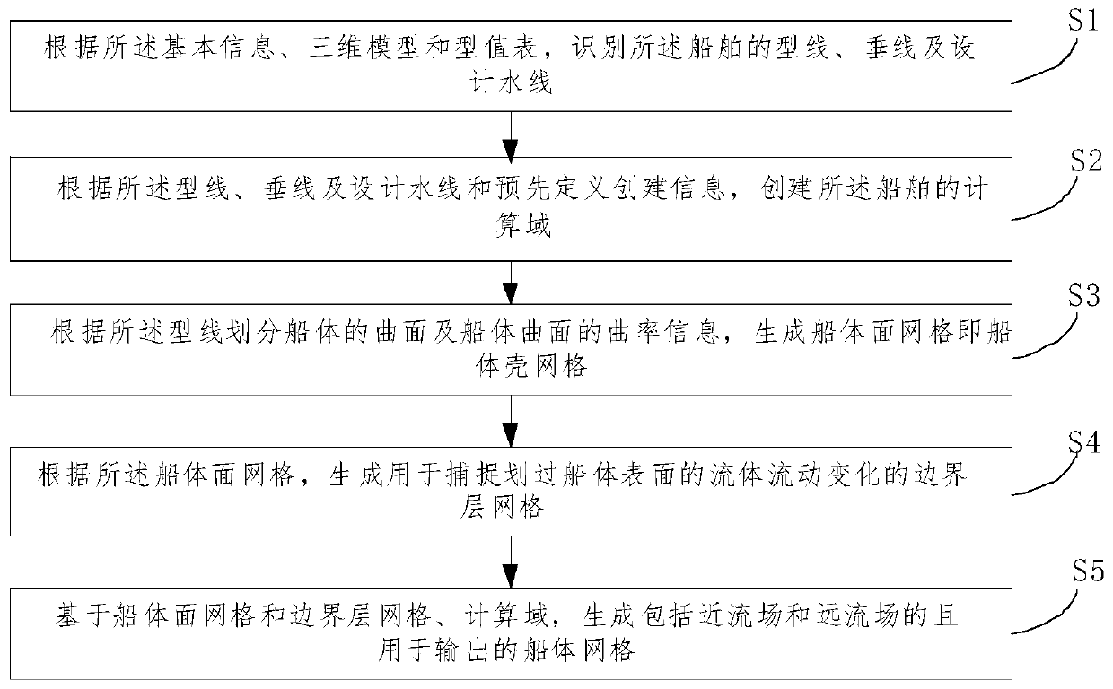
[0058] Such as figure 1 as shown, figure 1 A flow chart of a method for automatically dividing hull grids based on a virtual test platform provided by an embodiment of the present invention is shown. The method of this embodiment includes:

[0059]S1. According to the basic information, the three-dimensional model and the type value table, identify the shape line, vertical line and design waterline of the ship;

[0060] S2. Create a computational domain of the ship according to the molded line, vertical line, design waterline and predefined creation information.

[0061] For example, this step can include:

[0062] S21. Process the profiled line information of the profiled lines forming the hull surface according to the pre-numbered rules to obtain standardized numbers;

[0063] S22, judging whether the numbered hull is a stacked hull;

[0064] S23. According to the judging result of the stacked hull, create an external flow field calculation domain of the hull.

[0065] ...

Embodiment 2

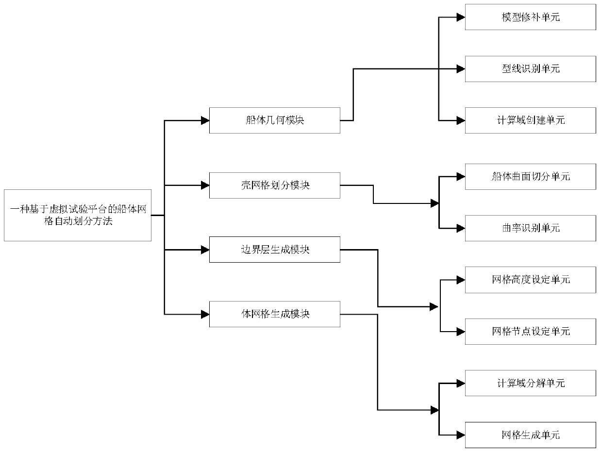
[0079] For a better understanding of the method in the above-mentioned embodiment one, as Figure 2 to Figure 12 The method of the present invention will be described in detail.

[0080] The system for implementing the aforementioned method mainly includes four modules: hull geometry module, shell mesh division module, boundary layer mesh generation module and volume mesh generation module.

[0081] (1) Hull geometry module

[0082] The hull geometry module mainly performs the import work of the 3D hull surface file. After the import, the 3D hull surface rotates, translates, and zooms in the system, as well as the topology modification of the hull geometry model. , creating the outer water domain of the hull. This module is mainly to ensure the correct import of the hull surface model and the reasonable configuration of the virtual test platform.

[0083] (2) Shell meshing module

[0084] The hull meshing module mainly divides the hull into a series of small surfaces accor...


PUM


Abstract

The invention discloses a hull grid automatic division method based on a virtual test platform. The method comprises the following steps: S1, identifying a molded line, a vertical line and a design waterline of a ship according to basic information, a three-dimensional model and a molded value table; s2, creating a calculation domain of the ship according to the molded line, the vertical line, thedesign waterline and predefined creation information; s3, dividing a curved surface of a hull and curvature information of the curved surface of the hull according to the molded line to generate hullsurface grids; s4, according to the hull surface grid, generating a boundary layer grid for capturing flow change of the fluid passing through the surface of the hull; and S5, based on the hull surface grid, the boundary layer grid and the computational domain, generating a hull grid which comprises a near flow field and a far flow field and is used for outputting. The method can adapt to automatic generation of grids of most ship types, the grid generation time during ship CFD calculation is saved, and a foundation is laid for finally achieving systematic numerical optimization of the ship types.

Description

technical field [0001] The invention relates to the field of virtual test platforms, in particular to a method for automatically dividing hull grids based on virtual test platforms. Background technique [0002] In recent years, the application of CFD technology in ship hydrodynamics has become more and more mature, and the research on ship resistance, propulsion, maneuverability, seakeeping and ship shape optimization using CFD technology has become more and more extensive. At the same time, in order to ensure the reliability and credibility of the calculation results, it is necessary to conduct in-depth research on the relevant factors that affect the numerical simulation. In the CFD software based on the finite volume method and the finite element method, when the truncation error of the discrete format is determined, the density of the grid and its distribution characteristics become the key factors to determine the discrete error. [0003] At present, although some res...

Claims


Application Information

Patent Timeline
Patent Type & Authority Applications(China)
IPC IPC(8): G06F30/15G06F30/23
CPCY02T90/00
Inventor 王晓原夏媛媛姜雨函朱慎超张兰赵新越张露露
Owner 智慧航海(青岛)科技有限公司
Why Eureka
Try Eureka