Extrusion type round can processing device
A processing device and extrusion technology, applied in the direction of feeding device, positioning device, storage device, etc., can solve the problems of time-consuming, cumbersome and complicated process, and secondary pollution of products, so as to simplify the production process and improve production efficiency Effect
- Summary
- Abstract
- Description
- Claims
- Application Information
AI Technical Summary
Problems solved by technology
Method used
Image
Examples
Embodiment 1
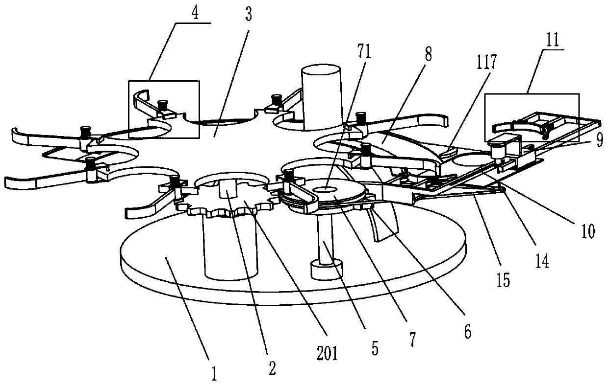
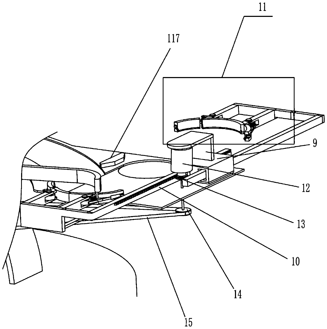
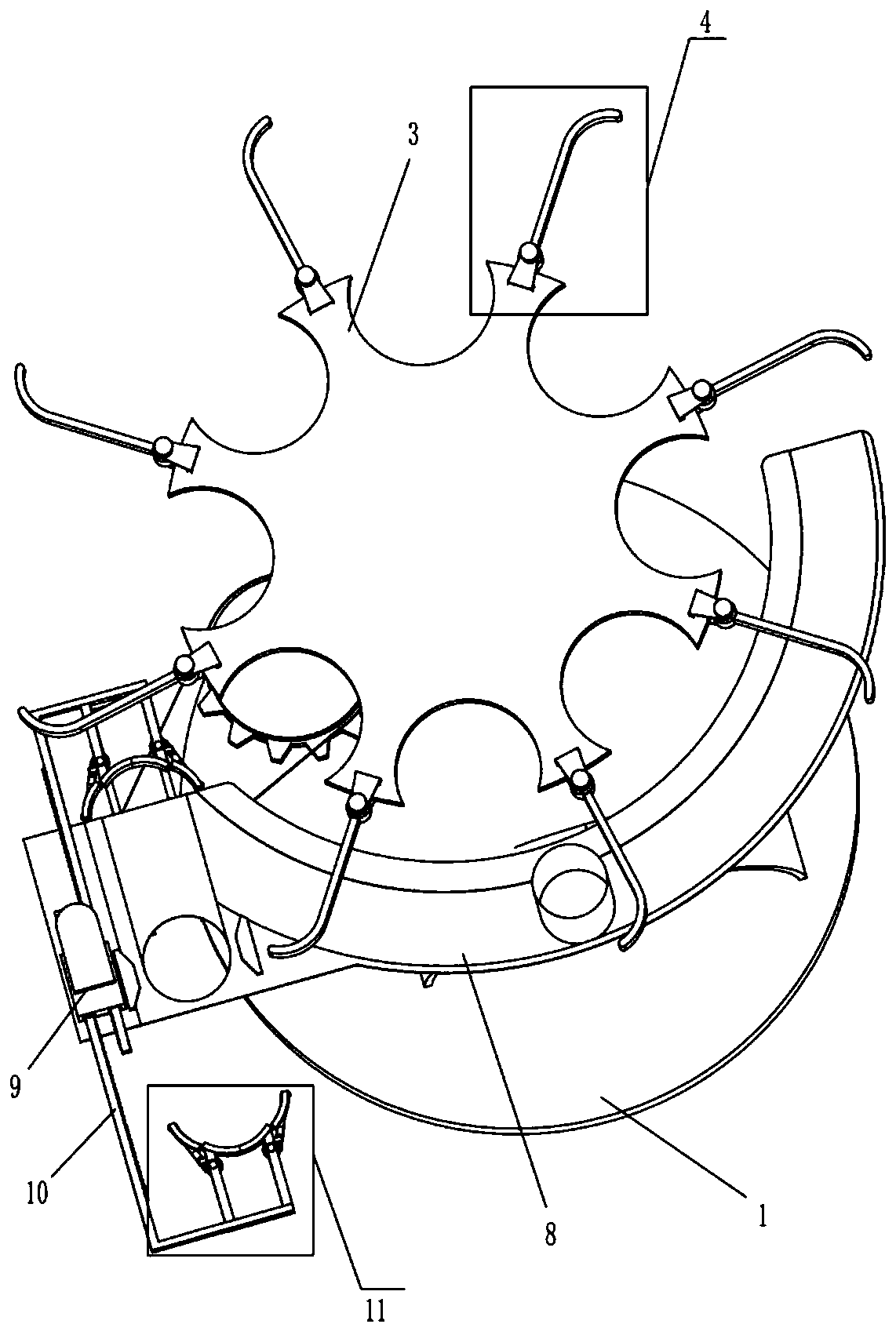
[0022] An extrusion type round can processing device, such as Figure 1-4 As shown, it includes a base plate 1, a first rotating shaft 2, a transmission gear 201 and a rotating disk 3. The upper side of the front part of the base plate 1 is rotatably connected with the first rotating shaft 2, and the middle part of the first rotating shaft 2 is fixedly connected with the transmission gear 201. The first rotating shaft 2. The upper end is fixedly connected with a rotating disk 3; a toggle mechanism 4, a second rotating shaft 5, a sector gear 6, a first transmission pulley 7, an overrunning clutch 71, a slideway plate 8, a two-way slideway 9, a sliding rack 10, and a sliding rod 101, the sliding sleeve 102 and the extruding mechanism 11, eight toggle mechanisms 4 are arranged at equal intervals on the edge of the rotating disk 3, the second rotating shaft 5 is fixedly connected to the bottom plate 1, and the second rotating shaft 5 is located on the right side of the first rotati...
Embodiment 2
[0029] On the basis of embodiment 1, a kind of extrusion type round can processing device, such as Figure 7 Shown, also include support 16, support plate 17, baffle plate 18, sliding plate 181, place bucket 19 and connecting rod 20, base plate 1 right upper side is affixed with support 16, and support 16 upper end is affixed with support plate 17 , the left part of the support plate 17 has a slot hole, the size of the slot hole is the same as that of the iron sheet, two baffle plates 18 are fixedly connected on the support plate 17, and the two baffle plates 18 are arranged in parallel to form a channel, and the channel is slidingly fitted with a sliding Plate 181, the upper side of two baffle plates 18 is affixed with placement bucket 19, the right side of sliding plate 181 is affixed with connecting rod 20, and the left end of the lower part of connecting rod 20 is affixed to fixed plate 111.
[0030] After the round can is placed on the slideway plate 8, the iron sheet is ...
Embodiment 3
[0032] On the basis of Example 2, such as Figure 8 As shown, it also includes a support rod 21, a fixed rod 22, a first clamping plate 23 and a second clamping plate 24, the left side of the connecting rod 20 is fixedly connected with a support rod 21, and the upper side of the support rod 21 is fixedly connected with a fixed rod 22. A first splint 23 and a second splint 24 are fixedly connected to the support plate 22 , and the first splint 23 and the second splint 24 are located below the supporting plate 17 .
[0033] When the two extrusion mechanisms 11 move towards each other, the connecting rod 20 is driven to move to the left, and the connecting rod 20 drives the fixed rod 22 to move to the left through the support rod 21. At this time, the first splint 23 and the second splint 24 on the fixed rod 22 Then move to the left to clamp the round can, so as to realize the function of fixing the round can and preventing it from moving left and right.
PUM
 Abstract
Description
Claims
Application Information
 - R&D
- Intellectual Property
- Life Sciences
- Materials
- Tech Scout
- Unparalleled Data Quality
- Higher Quality Content
- 60% Fewer Hallucinations
Browse by: Latest US Patents, China's latest patents, Technical Efficacy Thesaurus, Application Domain, Technology Topic, Popular Technical Reports.
© 2025 PatSnap. All rights reserved.Legal|Privacy policy|Modern Slavery Act Transparency Statement|Sitemap|About US| Contact US: help@patsnap.com


