A Micro Friction Stir Welding Process for Electronic Packaging

A friction welding and electronic packaging technology, applied in welding equipment, non-electric welding equipment, manufacturing tools, etc., can solve the problems of high density and pollution-free effect, and achieve good application prospects, high processing efficiency, and improved mechanics. performance effect

Active Publication Date: 2021-10-19
HARBIN INST OF TECH
View PDF7 Cites 0 Cited by
  • Summary
  • Abstract
  • Description
  • Claims
  • Application Information

AI Technical Summary

Problems solved by technology

[0005] The purpose of the present invention is to solve the problem of unsatisfactory high-density and pollution-free effect of the existing electronic packaging technology, and the problem that the existing friction stir welding technology is difficult to realize direct welding of micro, small and thin structures, and further provides A Micro Friction Stir Welding Process for Electronic Packaging

Method used


Image

  • A Micro Friction Stir Welding Process for Electronic Packaging
  • A Micro Friction Stir Welding Process for Electronic Packaging
  • A Micro Friction Stir Welding Process for Electronic Packaging

Examples


specific Embodiment approach 1

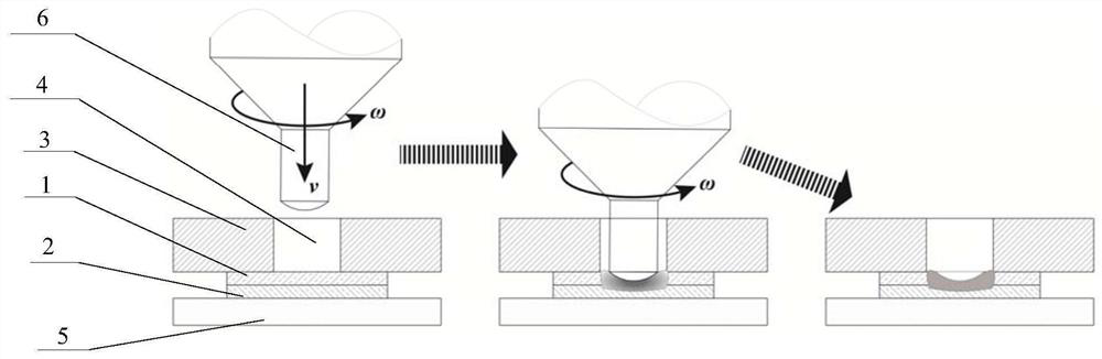
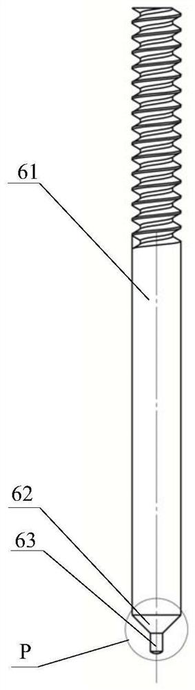
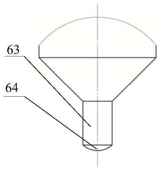
[0024] Specific implementation mode one: combine Figure 1~6 Describe this embodiment, a micro-stir friction welding process for electronic packaging. First, the first pad 1 and the second pad 2 to be welded are a group of pads. When the pads are arranged in a single point , the press-in hole 4 is prefabricated on the first substrate 3, and the pad group is arranged in parallel between the first substrate 3 and the second substrate 5, and the center position of the press-in hole 4 is aligned with the pad group Arrange in the center, then use the clamp to press the first substrate 3 and the second substrate 5, align the stirring head 6 coaxially above the pressing hole 4, control the stirring head 6 to rotate at a high speed and move down into the pressing hole 4, Then press it into the first pad 1, and realize the permanent metallurgical connection between the first pad 1 and the second pad 2 under the set press-in amount and holding time, and finally control the stirring head...


PUM


Abstract

The invention relates to a micro-stir friction welding process for electronic packaging, which belongs to the technical field of electronic packaging. The invention solves the problem of unsatisfactory high-density and pollution-free effects of the existing electronic packaging technology, and the difficulty of direct welding of micro, small and thin structures by the existing friction stir welding technology. First, the first pad and the second pad to be soldered are a set of pad groups. When the pad group is arranged in a single point, press-in holes are prefabricated on the first substrate, and the pad groups are arranged in parallel. Between the first substrate and the second substrate, align the press-in hole with the center of the pad group, then use the clamp to press the first substrate and the second substrate, and align the stirring head coaxially on the press Above the insertion hole, control the stirring head to rotate at a high speed and move down into the pressing hole, and then press into the first pad. Under the set pressing amount and load holding time, the first pad and the second pad are realized. The permanent metallurgical connection between the discs, and finally the control of the stirring head moving up and out of the press-in hole.

Description

technical field [0001] The invention relates to a micro-stir friction welding process for electronic packaging, belonging to the technical field of electronic packaging. Background technique [0002] With the rapid development of information technology and electronic industry, electronic products are increasingly integrated into daily life, such as mobile communication equipment, computers, etc. are widely used; on the other hand, in aerospace, intelligent transportation and national defense military In the high-tech field, electronic products also play an irreplaceable role. These applications require electronic products to be smaller, lighter, higher density, better performance, and more reliable, which drives the rapid development of integrated circuit packaging and electronic packaging technology, which puts forward two key points for the current electronic packaging field Sexual science issues: high-density and pollution-free. [0003] The first is high density. The p...

Claims


Application Information

Patent Timeline
Patent Type & Authority Patents(China)
IPC IPC(8): B23K20/12
CPCB23K20/122B23K2101/36
Inventor 谢聿铭黄永宪孟祥晨万龙
Owner HARBIN INST OF TECH
Why Eureka
Try Eureka