A kind of plastic pipe and its processing device and process

A processing device and a technology for plastic pipes, which are applied in the field of plastic pipe processing to achieve the effect of preventing fluid flow from being sluggish.

Active Publication Date: 2020-09-15
广东恒畅塑料管材有限公司
View PDF1 Cites 0 Cited by
  • Summary
  • Abstract
  • Description
  • Claims
  • Application Information

AI Technical Summary

Problems solved by technology

However, this patent cannot smooth the interior of the butt joint when two plastic pipes are joined

Method used


Image

  • A kind of plastic pipe and its processing device and process
  • A kind of plastic pipe and its processing device and process
  • A kind of plastic pipe and its processing device and process

Examples


specific Embodiment approach 1

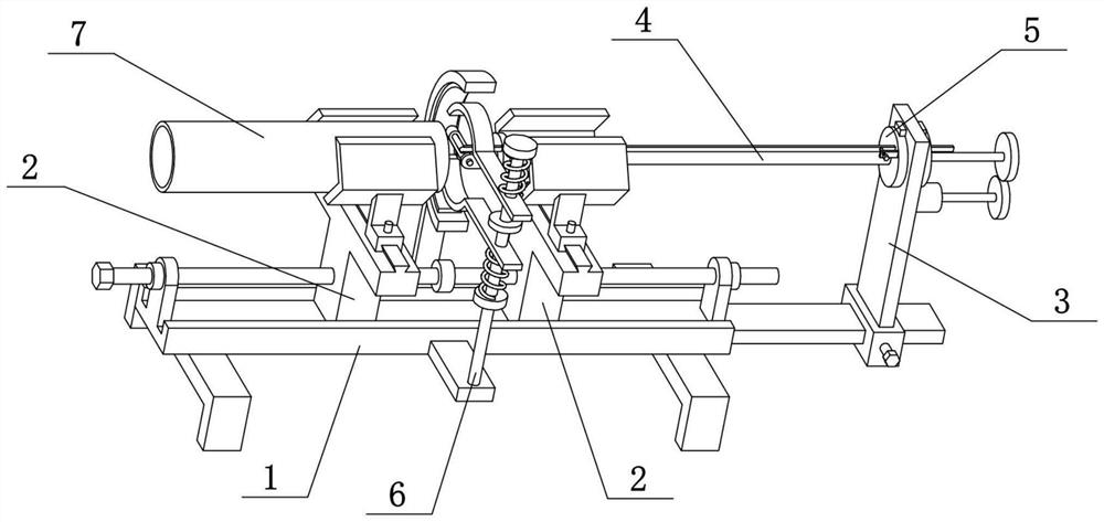
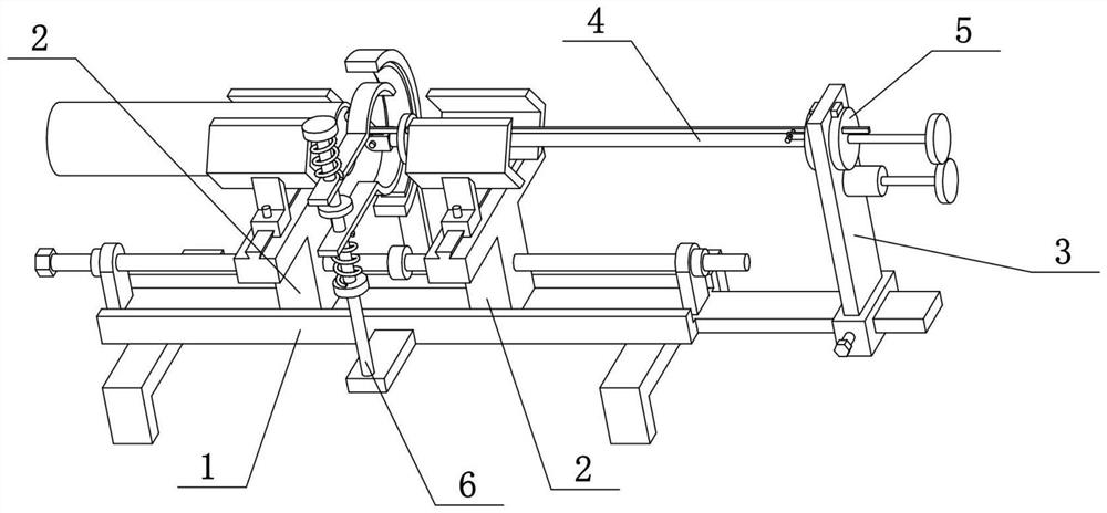
[0032] Combine below Figure 1-7 Describe this embodiment, the present invention relates to the field of plastic pipe processing, more specifically, a plastic pipe and its processing device and process, including the extension shaft 4, hinged seat 401, sliding hole 402, rotating column 403, sliding cylinder 404 , support plate 405 and push-pull thin rod 406, the present invention can carry out docking of two plastic pipes, and can smooth the inside of the docking position during docking, preventing the liquid from flowing smoothly due to the protrusion of the docking position.

[0033] The left end of the extension shaft 4 is provided with a hinge seat 401, the hinge seat 401 is hingedly connected with a rotating column 403, the rotation column 403 is provided with a slide hole 402, and the left part of the insertion shaft 4 is fixedly connected with a push-pull thin rod 406, The push-pull thin rod 406 is slidably connected on the support plate 405, and the push-pull thin rod ...

specific Embodiment approach 2

[0035] Combine below Figure 1-7 To illustrate this embodiment, the plastic pipe processing device also includes a thick shaft 5, a convex plate 501 and a fastening screw III502. The right end of the inserted shaft 4 is fixedly connected to the left center of the thick shaft 5, and the right end of the thin rod 406 is pushed and pulled. Slidingly connected on the thick shaft 5, the left side of the thick shaft 5 is fixedly connected with a convex plate 501, and the convex plate 501 is threadedly connected with a fastening screw III502, and the fastening screw III502 pushes against the push-pull thin rod 406. The push-pull thin rod 406 can slide left and right on the thick shaft 5 to adjust the left-right position of the push-pull thin rod 406, and the left-right position of the push-pull thin rod 406 can be fixed by turning the fastening screw III502.

specific Embodiment approach 3

[0037] Combine below Figure 1-7 To illustrate this embodiment, the plastic pipe processing device also includes a vertical moving plate 3, a circular through hole 303 and a stop piece 503, the upper part of the vertical moving plate 3 is provided with a circular through hole 303, and the thick shaft 5 is rotatably connected to the circular On the circular through hole 303, two limiting pieces 503 are fixedly connected to the outside of the circular through hole 303, and the two limiting pieces 503 are respectively located on the left and right sides of the vertically moving plate 3. The thick shaft 5 can rotate on the circular through hole 303 on the upper part of the vertical moving plate 3 with its own axis as the axis, and then drive the extending shaft 4 to rotate around its own axis, and then the rotating column 403 also rotates around the axis of the extending shaft 4 For pivoting, the interior of the butt joint of the two plastic tubes 7 is smoothed. The function of t...


PUM


Abstract

The invention relates to a plastic pipe and its processing device and process. The plastic pipe is composed of the following raw materials in parts by weight: 2 parts of polyethylene terephthalate, 1 part of polystyrene, 1 part of acrylic acid, and 1 part of polycarbonate ;The process is: Step 1: Clamp and fix the two plastic tubes on the upper parts of the two T-shaped slides, so that the two T-shaped slides are close to butt; Step 2: The heating wire on the heating ring is connected to the two plastic tubes. Heating the docking position; Step 3: Adjust the left and right position of the end of the push-pull thin rod, so that the end of the push-pull thin rod is aligned with the inner docking position of the two plastic tubes; Step 4: Make the extension shaft rotate on its own axis , and then the rotating column also rotates around the axis extending into the shaft to smooth the inside of the butt joint position of the two plastic pipes.

Description

technical field [0001] The invention relates to the field of plastic pipe processing, in particular to a plastic pipe and its processing device and process. Background technique [0002] The application number is CN201811312354.4, which discloses a mold for plastic pipe processing. The invention relates to the field of plastic pipe processing equipment, specifically a mold for plastic pipe processing, including an anti-chip sleeve, a protective structure, a molding sleeve, and a driving gear. , two guide shafts, multiple cooling tanks, guide structures and dismounting tanks; one end of the forming sleeve for winding and processing the cylindrical structure of the plastic pipe is fixed with a driving gear for transmission; the other end of the forming sleeve and the driving gear are both A guide structure is fixed; the guide shaft is rotatably connected with the forming sleeve through the guide structure; the guide shaft is provided with an anti-chip sleeve for sealing the di...

Claims


Application Information

Patent Timeline
Patent Type & Authority Patents(China)
IPC IPC(8): B29C65/18B29C65/78B29L23/00
CPCB29C65/18B29C65/7841B29C66/5221B29L2023/22
Inventor 史春龙
Owner 广东恒畅塑料管材有限公司
Why Eureka
Try Eureka