Mechanical ventilation countercurrent wet cooling tower group of rain area structure

A wet cooling and mechanical ventilation technology, applied in the field of cooling towers, can solve the problems of increasing the ventilation volume of the leeward tower and the low heat exchange efficiency of the leeward side of the cooling tower group, so as to solve the problems of low cooling efficiency, reducing flow stagnation, and reducing the scope of influence. Effect

Active Publication Date: 2022-05-31
SHANDONG UNIV
View PDF5 Cites 0 Cited by
  • Summary
  • Abstract
  • Description
  • Claims
  • Application Information

AI Technical Summary

Problems solved by technology

[0006] Aiming at the deficiencies in the prior art, the object of the present invention is to provide a mechanically ventilated counterflow wet cooling tower group with a rain zone structure. The ambient wind can flow between the windward towers, and can also enter the leeward tower through the windward tower, increase the ventilation volume of the leeward tower, balance the aerodynamic field in the tower, reduce the ventilation resistance in the rain area of ​​the tower group, and solve the problem of existing cooling towers. The problem of low heat transfer efficiency inside the cluster and on the leeward side

Method used


Image

  • Mechanical ventilation countercurrent wet cooling tower group of rain area structure
  • Mechanical ventilation countercurrent wet cooling tower group of rain area structure
  • Mechanical ventilation countercurrent wet cooling tower group of rain area structure

Examples


Embodiment 1

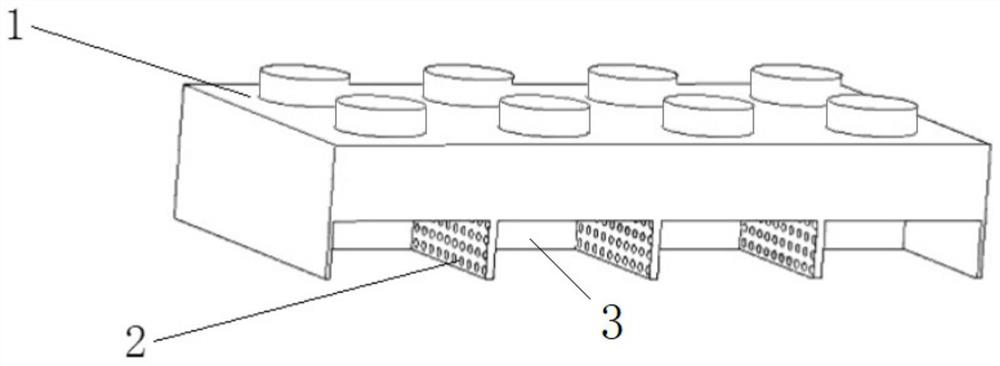
[0033] In a typical embodiment of the present invention, such as figure 1 As shown, a mechanical ventilation counterflow wet cooling tower group with rain area structure is proposed, including several rows of cooling tower groups, each row of cooling tower groups is provided with a plurality of cooling tower bodies 1, and the cooling tower groups form a mechanical ventilation counterflow wet cooling tower group (hereinafter referred to as the mechanical tower group).

[0034] The cooling tower body 1 is provided with a tower core element inside. The tower core element includes a spray area, a filler and a rain area. The spray area is located on the upper part of the rain area, and the filler is arranged between the spray area and the rain area.

[0035] The cooling tower bodies of the mechanical tower group are arranged adjacently, and the rain areas of adjacent cooling tower bodies are separated by tower walls, and the tower walls between the rain areas of adjacent cooling to...

Embodiment 2

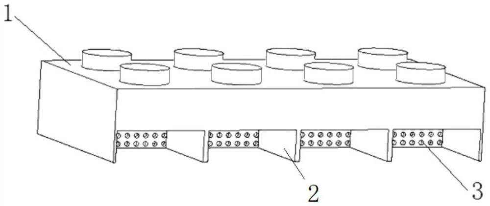
[0050] Such as figure 2 As shown, in the present embodiment, the second tower wall 3 spaced between the cooling tower groups is set as a porous structure, and the second tower wall 3 is arranged horizontally to connect the first tower wall 2 between the rain areas of the mechanical tower group. .

[0051] Specifically, this embodiment is a group of back-to-back mechanical towers. The mechanical towers in the mechanical tower group have single-sided air intake and are arranged in a back-to-back form. There are 4 mechanical towers in each row, arranged in 2 rows, and a total of 8 mechanical towers.

[0052] The transverse wall between the mechanical tower group rain areas is a porous structure, that is, the second tower wall 3 is a porous structure, and the porosity is set according to the operating conditions of the mechanical tower group, local prevailing wind speed, wind direction, and air temperature. The setting interval is Between 0.2 and 1.

[0053] The second tower wa...

Embodiment 3

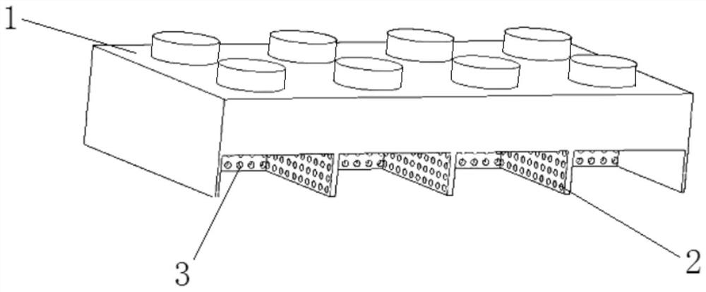
[0058] Such as image 3 As shown, what is set as the porous structure in the present embodiment is the first tower wall 2 and the second tower wall 3 between the rain areas of the mechanical tower group, wherein the first tower wall 2 is arranged vertically, and the second tower wall 3 is horizontally arranged. It is set to connect the first tower wall 2 between the rain areas of the mechanical tower group through the second tower wall 3 .

[0059] Specifically, this embodiment is a group of back-to-back mechanical towers. The mechanical towers in the mechanical tower group have single-sided air intake and are arranged in a back-to-back form. There are 4 mechanical towers in each row, arranged in 2 rows, and a total of 8 mechanical towers.

[0060] The horizontal wall and vertical wall between the mechanical tower group rain areas are all porous structures, that is, the first tower wall 2 and the second tower wall 3 are porous structures, and the porosity depends on the operat...


PUM


Abstract

The invention discloses a mechanical ventilation countercurrent wet cooling tower group of a rain area structure, which belongs to the technical field of cooling towers, and comprises a plurality of rows of cooling tower groups, each row of cooling tower group is provided with a plurality of cooling tower bodies, and the cooling tower bodies are adjacently arranged; a tower core element is arranged in the cooling tower body, and the tower core element comprises a spraying area, a filler and a rain area which are sequentially arranged from top to bottom; the rain areas of the adjacent cooling tower bodies are separated through tower walls, and the tower walls are arranged to be of a porous structure so as to facilitate flowing of environmental wind.

Description

technical field [0001] The invention relates to the technical field of cooling towers, in particular to a group of mechanically ventilated counterflow wet cooling towers with a rain zone structure. Background technique [0002] The statements herein merely provide background information related to the present invention and do not necessarily constitute prior art. [0003] As a kind of heat exchange equipment, cooling tower is widely used in electric power, metallurgy, refrigeration and other fields. Its working principle is to transfer the circulating water carrying industrial waste heat to the atmosphere in the tower to realize the cooling of circulating water. [0004] According to the form of ventilation, cooling towers can be divided into natural ventilation cooling towers and mechanical ventilation cooling towers. Due to its small size and flexible working condition adjustment mechanism, mechanical draft cooling towers have received more and more attention. Mechanical...

Claims


Application Information

Patent Timeline
Patent Type & Authority Applications(China)
IPC IPC(8): F28C1/02F28F25/10F28F25/02
CPCF28C1/02F28F25/10F28F25/02F28F2025/005Y02B30/70
Inventor 孙奉仲邓伟鹏张晓宇陈学宏
Owner SHANDONG UNIV
Why Eureka
Try Eureka