
Variable print control bars

A printing head and inkjet printing machine technology, applied in printing, printing devices, electrical components, etc., can solve problems that affect the analysis and processing of nozzle test patterns, distortion, and irregularity of substrate conveying in printing machines, etc.

Active Publication Date: 2020-06-05
HEIDELBERGER DRUCKMASCHINEN AG
View PDF8 Cites 3 Cited by
  • Summary
  • Abstract
  • Description
  • Claims
  • Application Information

AI Technical Summary

Problems solved by technology

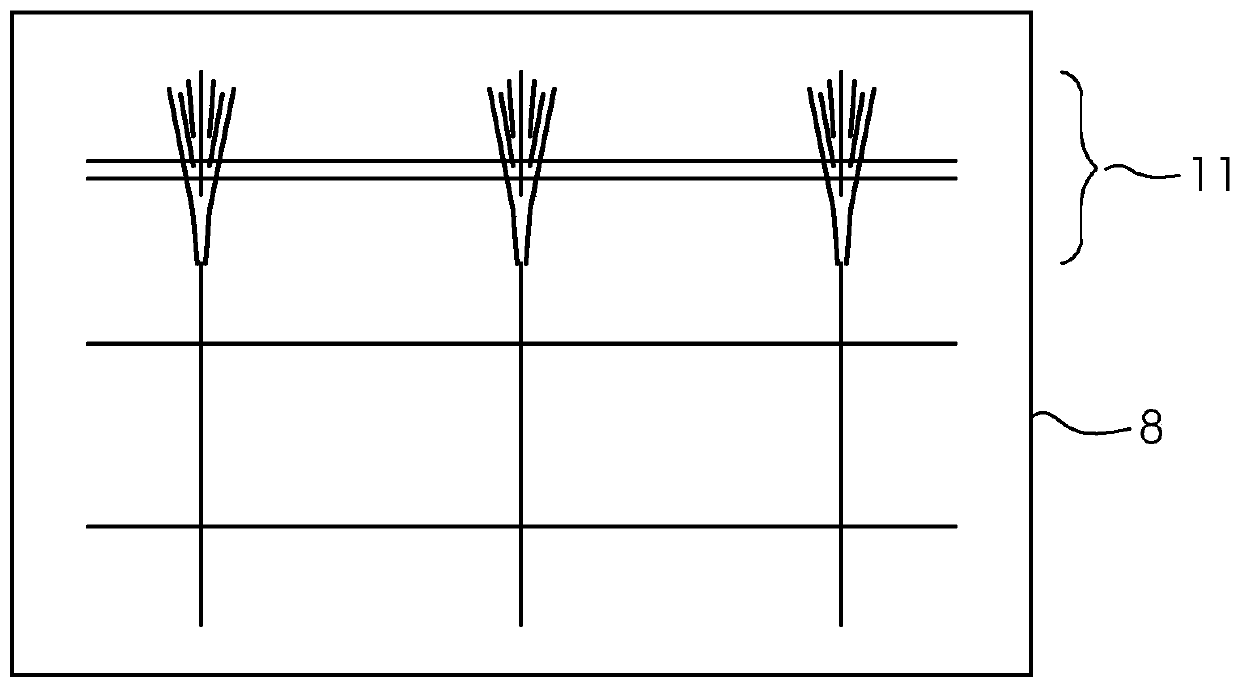
[0004] A very unique problem that negatively affects monitoring in this regard is: irregularities in the substrate transport in the printing press
The problem here is that the edges of the sheet vibrate, which in turn causes distortions in the digital image produced by the image detection system (Verzerrung)
Such distortions of course also affect the analytical processing of nozzle test pattern patterns
Here, the closer the line (Zeile) of the nozzle test pattern is to the rear edge of the sheet, the stronger the distortion
Such distortions make it impossible or significantly more difficult to reliably analyze the nozzle test pattern for accurate detection of defective printing nozzles.

Method used


Image

  • Variable print control bars
  • Variable print control bars
  • Variable print control bars

Examples


Embodiment Construction

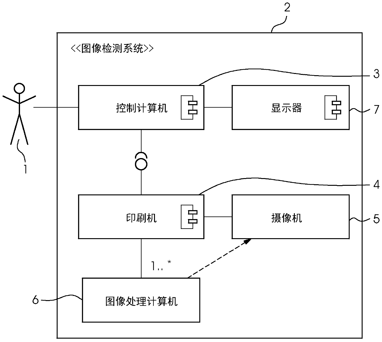
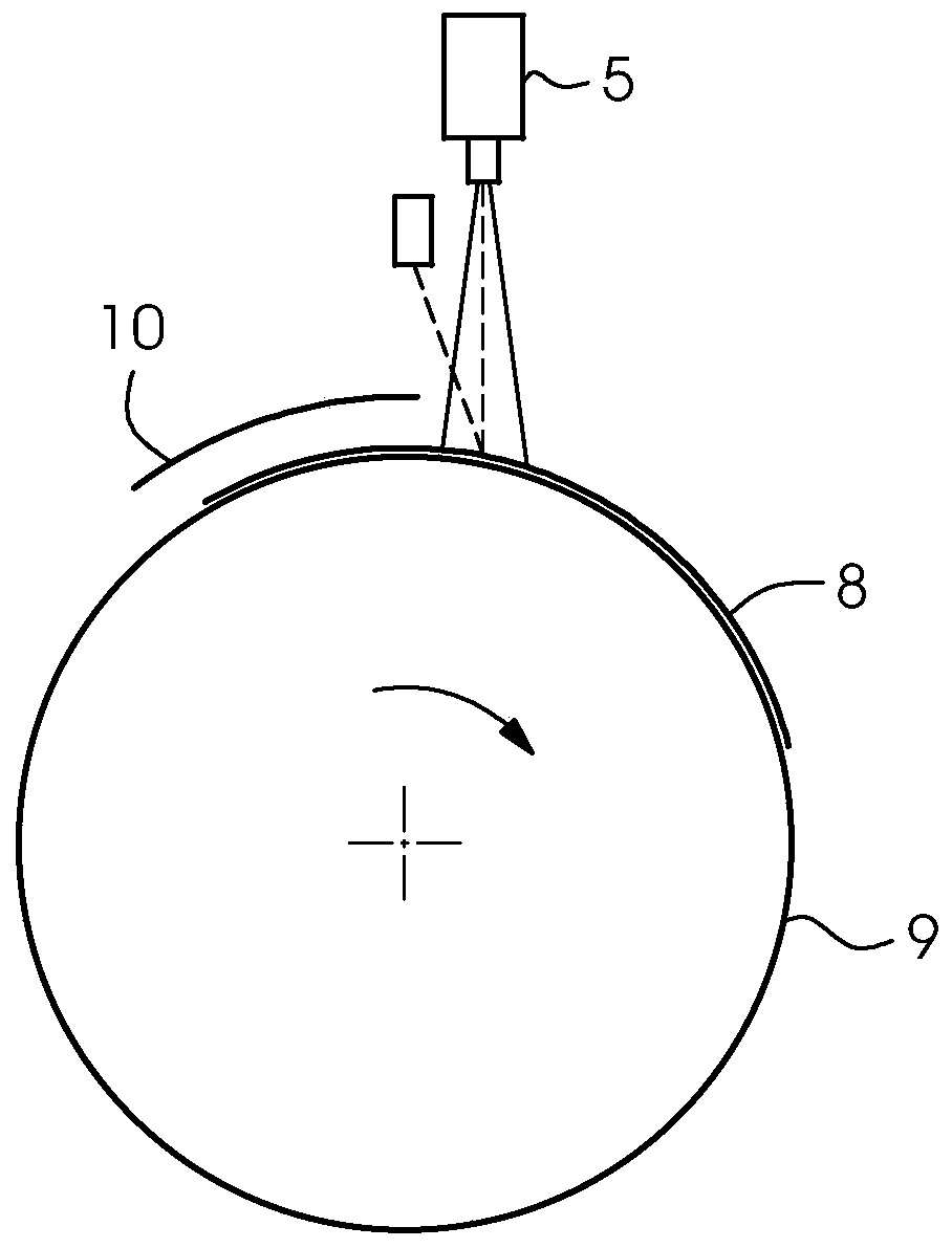
[0023] figure 1 An example of an image detection system 2 adopting the method according to the present invention is shown. The image detection system 2 includes at least one image sensor 5 which is usually a camera 5 integrated into the sheet printing press 4. In this way, at least one camera 5 captures the printed images produced by the printing press 4 and sends the data to the computers 3, 6 for analysis and processing. The computers 3, 6 can be their own separate computers 6 (for example, one or more specialized image processing computers 6) or can be the same as the control computer 3 of the printing press 4. At least the control computer 3 of the printing press 4 has a display 7 on which the results of the image monitoring are displayed to the user 1.

[0024] When transporting the printing sheet 8 in the inkjet printer, the above-mentioned reduction of the printing sheet will occur here, and this reduction of the printing sheet has a negative effect on the image capture o...


PUM


Abstract

The invention relates to a method for detecting the defective printing nozzles in a printing head of an inkjet printer by means of a computer. In order to detect, a plurality of rows of nozzle test pattern styles are printed on a printing substrate in a printing sheet form, the nozzle test pattern styles comprise a determined number n of horizontal rows which are composed of equidistant lines which are periodically and vertically printed and are arranged up and down in the printing direction, and in each row of nozzle test pattern patterns, only the nth printing nozzle of the printing head ofthe ink-jet printer is in an activated state and thus contributes to the line of the row of nozzle test pattern patterns. The printing nozzles in the activated state are added in a line-to-line manner, the nozzle test pattern is detected by at least one image sensor and is evaluated by a computer in order to determine a defective printing nozzle, and the horizontal rows, which consist of equidistant lines printed vertically periodically and are arranged one above the other in the printing direction, vary in sequence from the printing sheet to the printing sheet.

Description

Technical field [0001] The invention relates to a method for detecting defective printing nozzles in an inkjet printer by means of a changing printing inspection strip. [0002] The technical field to which the present invention belongs is quality inspection. Background technique [0003] In today's printing industry, especially in larger printing presses, quality inspections are performed automatically through so-called inline monitoring systems (also called image inspection systems). Inline in this case means that the image detection system (more precisely the camera of the image detection system) is installed in the printing press. Here, the camera is usually installed after the last printing mechanism or, if it exists, after another reprocessing station (such as a varnishing mechanism) and detects the printed products produced by the printing press. This can be a camera or a camera system with multiple cameras. Other image sensors are also feasible. But hereinafter referred...

Claims


Application Information

Patent Timeline
Patent Type & Authority Applications(China)
IPC IPC(8): B41J29/393B41J2/135
CPCB41J29/393B41J2/135B41J2029/3935H04N1/00002H04N1/00023H04N1/0005B41J2/16579B41J2/2142
Inventor R·蒂塔D·施特格迈尔M·迈尔G·容汉斯
Owner HEIDELBERGER DRUCKMASCHINEN AG
Learn More