
Integrated stretch-bending roof luggage rack for new energy automobile and forming process thereof

A new energy vehicle and molding process technology, which is applied to vehicle parts, electrolytic coatings, surface reaction electrolytic coatings, etc., can solve the problem of reducing the service life of the roof rack, the aesthetics of the whole vehicle, easy wear and corrosion, and poor installation and disassembly. Convenience and other issues, to achieve the effect of beautiful appearance, improved load strength and convenient operation

Pending Publication Date: 2020-06-05
NINGBO SHUNJIANG AUTO PARTS MFG
View PDF0 Cites 0 Cited by
  • Summary
  • Abstract
  • Description
  • Claims
  • Application Information

AI Technical Summary

Problems solved by technology

Most of the roof racks in the prior art are composed of multiple components, so their structures are usually complicated and inconvenient to install and disassemble.
Furthermore, because the roof rack is installed on the outside of the vehicle, it is prone to wear and corrosion under the conditions of perennial use and sun and rain, thereby reducing the service life of the roof rack and the appearance of the vehicle. sex

Method used


Image

  • Integrated stretch-bending roof luggage rack for new energy automobile and forming process thereof
  • Integrated stretch-bending roof luggage rack for new energy automobile and forming process thereof
  • Integrated stretch-bending roof luggage rack for new energy automobile and forming process thereof

Examples


Embodiment Construction

[0043] Embodiments of the present invention will be described in further detail below in conjunction with the accompanying drawings.

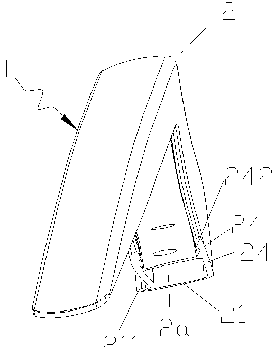
[0044] Figures 1 to 5 It is a structural representation of the present invention.

[0045] The reference signs are: luggage rack body 1, first hole 1a, second hole 1b, third hole 1c, fourth hole 1d, fifth hole 1e, sixth hole 1f, front support section 11, main body rod section 12. Rear support section 13, aluminum alloy profile rod 2, hollow cavity 2a, assembly cavity 2b, top panel 21, arc-shaped protrusion 211, left panel 22, left lower extension 221, left buckle 222, bottom panel 23 , the right panel 24 , the lower right extension 241 , and the right buckle 242 .

[0046] The roof luggage rack is a special device installed longitudinally on the left and right sides of the roof surface for placing articles. The roof luggage rack in the prior art is usually assembled from multiple parts, which not only causes the roof luggage rack to Disasse...


PUM


Abstract

The invention discloses an integrated stretch-bending roof luggage rack for the new energy automobile comprises. The rack comprises a luggage rack body, the luggage rack body is formed by machining analuminum alloy section bar, and the luggage rack body sequentially comprises a front supporting section, a main body rod section and a rear supporting section from front to back; the curvature of theluggage rack body is integrally formed through a three-dimensional stretch bending process, and the front supporting section of the luggage rack body is formed by machining the front end of a stretch-bent aluminum alloy section bar through a milling process. The rear supporting section of the luggage rack body is formed by processing the rear end of a bent aluminum alloy section bar through a milling process; an oxide film layer is formed on the outer surface of the luggage rack body; and a hole is formed in the bottom surface of the luggage rack main body rod section. The forming process ofthe integrated stretch-bending roof luggage rack of the new energy automobile comprises the steps of preparing an aluminum alloy section bar, stretch-bending the aluminum alloy section bar, sawing, milling, drilling, deburring, mechanically polishing, manually polishing and anodizing surface treatment.

Description

technical field [0001] The invention relates to the design and manufacturing technology of auto parts, in particular to a luggage rack installed on the roof of a car, in particular to a new energy vehicle integrated stretch-bending roof luggage rack and its forming process. Background technique [0002] The roof rack is a special device installed on the top of the vehicle for placing items. The roof luggage rack can carry a large amount of necessary items through the roof luggage rack when people are traveling, without occupying the space in the car. Roof racks usually consist of cross bars and support feet, one on the left and one on the roof. Most of the roof luggage racks in the prior art are composed of a plurality of components, so their structures are usually more complicated, and it is inconvenient to install and disassemble. Furthermore, because the roof rack is installed on the outside of the vehicle, it is prone to wear and corrosion under the conditions of peren...

Claims


Application Information

Patent Timeline
IPC IPC(8): B60R9/04B21D11/00B23P15/00C25D11/16C25D11/08C25D11/18
CPCB60R9/04B21D11/00B23P15/00C25D11/16C25D11/08C25D11/18
Inventor 姜志明
Owner NINGBO SHUNJIANG AUTO PARTS MFG
Learn More